

Introduction: Kindle 3 DIY Light


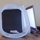

The Kindle 3 uses a screen technology that looks almost like glossy magazine print. What makes it remarkable and so easy to read is that it uses ambient light to illuminate the screen rather than a back light. The quality of the image is fantastic in normal reading conditions, but gets difficult to read in low light situations.
Amazon, in their great redesign of this product has thoughtfully included an in-built power source to run a light. For a mere $60 Amazon provides a light-equipped leather cover that can tap into the power source.
This Instructable will show you how to tap into the power source and build your own lighted cover.
Difficulty: Moderate
For some reason the photo notes feature broke half way through this instructable. If something is unclear, please post a question and I will do my best to clarify. Hopefully the feature will be unbroken in the future and I can add some more helpful notes.
(By the way, I haven't been here in a while and I'm disappointed to find that Instructables is trying to sell "PRO" formatting features to the people that actually GENERATE their content for FREE. Lame.)
TOOLS:
* Google SketchUp (not needed, but helpful for viewing and manipulating plans)
* printer
* dremel tool with rotary cutting, routing, and grinding bits
* vice
* safety glasses
* ear protection
* assorted files
* scissors
* hobby knife
* soldering iron
* drill and assorted bits
* multi-meter
* small clamps
* coping saw
MATERIALS:
* 1.5 mm stainless steel sheet
* 6.5 mm bass wood sheet
* 2.5 mm bass wood sheet
*160 x 230 x 23 mm hard cover book (W x L x H outside dimensions)
* heavy cardboard/plastic sheet
* braided elastic band
* glue stick
* gorilla glue
* 2.5mm screws
* 2x 3mm bright white LEDs
* 3x 1K ohm resistors
* 3x 220 ohm resistors
* stranded hookup wire
* proto board
* SPST or DPDT micro switch (SPST for on/off) (SP Three Throw for low, off, high) RSOnline.co.uk Part 718-2317 or similar
* solder
Some Useful Information for other K3 Hackers:
Dimensions:
* Top power port 6mm wide x 8mm deep
* Bottom power port 5mm x 8mm
* Clips ~ .5mm thick
*~114 mm between ports
Electrical:
* Top port - +4V
* Bottom port - ground
Step 1: Create the Clips


The Amazon lighted cover uses two small brass clips to hold the K3 to the cover. The kindle slides first onto the bottom clip at an angle and then a spring-loaded hook attaches to the top port. My solution uses the elastic band in the upper right corner to secure the kindle instead of the spring-loaded clip.
Check out the lighted cover instructions from amazon for a better idea how the clips work.
1) Use the attached PDFs as a template to create the clips. Print out each template and use a hobby knife to cut a template free. Use a glue stick to attach the template to the 1.5 mm stainless steel plate. NB! The PDFs are set for A4 paper and should print to the appropriate scale if A4 paper is chosen.
2) Cut the rough form using a cutting bit in a dremel tool.
3) Use the grinding tool to remove excess material and shape the clip. It may be necessary to apply a new template if it becomes scorched or damaged.
4) Use a grinding bit to remove around .5 mm from each side of the portion that will attach to the kindle, leaving the rest of the clip intact. To make this easier, I fastened the clip into a vice and only allowed the portion I wanted to grind to stick out.
5) Check your dimensions against the diagrams below.
6) Test your clips by gently pushing them into the ports. The lower clip should rotate upward as it slides into the port. The clips should slide into the ports with very little resistance. If it does not slide easily, grind the clip down and compare it to the printed templates.
7) Switch the kindle on and set your mulit-meter for DC voltage and check the voltage across the two clips. It should be around 4V. The top port should be positive and the bottom ground. If there is no voltage across the clips, ensure the kindle is on. When it is in sleep mode, the light will automatically turn off. I also found that when my bottom clip was slightly too short, it did not properly make contact.
8) Carefully drill 3mm holes in the clips. A drill press and machine oil will help greatly in this process.

Step 2: Create the Clip Mounting Bracket


To secure the clips to the Kindle and provide a method for tapping into the power, a mounting bracket of some sort is necessary.
1) Use the PDF below for dimensions of the bracket. A sketchup file is also included for reference.
2) Cut the 6.5 mm basswood into a 15 x 130 mm length.
3) Use a router, or a hobby knife to remove two rectangles of 9 x 14 mm from each end. Locate the reliefs 5 mm from each end. A square file is very useful for removing the excess material.
4) Frequently check the size of the rectangle against your clips to ensure a snug fit.
5) Use a dremel tool milling bit or a hobby knife to create a 1-2 mm channel between the two clips through which wires can be routed.
6) Within the channel, drill two holes through to the bottom of the bracket. I drilled the holes at 45 degrees to limit the stress on the wire. 90 degree turns are hard on the insulation and wiring.
7) Cut a sheet of 2.5 mm bass wood to 15 x 130 mm to create a top.
8) Drill small pilot holes for the screws.
9) Strip off around 15 mm of insulation from each wire.
10) Push the screws through the 2.5 mm bass wood and turn the wood upside down so the screw heads are touching the table.
11) drop each clip into place over the screws. Make sure the top clip and bottom clip are properly oriented! See the picture below.
12) Wrap the wire around the screw. Make a solid wrap. This will be the electrical connection with the kindle. Soldering to stainless steel is very difficult, so I opted for a mechanical connection instead.
13) Dampen the 6.5 mm and 2.5 mm pieces of wood with a moist paper towel. A bit of water helps the gorilla glue work better.
14) Spread a small amount of gorilla glue across the two pieces. Push the two pieces together and carefully route the wires through the channels you made. Be sure to pull the wires through the holes!
15) Screw down all three screws and tightly clamp the piece with two small clamps.

Step 3: Create the Light Base


Build a base to house the light circuit, lights and switch
1) Print out and cut out the attached PDF template and use a glue stick to fasten this to the 6.5 mm bass wood. 6 mm plywood may be a better choice if available because it is much more sturdy.
2) Drill relief holes in each corner of the inside rectangle. This will allow you to insert a coping saw as well as prevent the wood from splitting as you cut.
3) Use a coping saw or similar tool to cut out the inside of the rectangle and the area to the left. The small connecting rectangle will be filed out to provide a path for routing wires to the switch. Do not cut there!
4) Orient the open end to the right; this will house the switch. On the bottom, use a file or exacto blade to remove the a rectangle of wood approximately 5 mm wide and 2 mm deep between the switch opening and the circuit area.
NB! The pdfs are formated for A4 paper!
Step 4: Create the Light Hood


To house the LEDs and, use .3 mm brass plate to create a light hood. The light hood comes in two pieces: a hood to cover and protect the lights and a plate that holds the LEDs.
1) Print out the attached PDF template and fasten it to a sheet of .3 mm brass plate.
2) Using tin snips carefully cut out the outline of the shapes.
3) Use a vice or something similar to bend the brass. I bend with the lines on the inside. I didn't have a vice so I used two pieces of wood bolted together.
4) The long edge of the hood is particularly difficult to bend because it interferes with bending the sides. Use a pair of padded pliers to gently bend this section. In the finished product, tool marks can be clearly seen where the pliers were used to bend the metal.
5) Bend the LED plate in the vice.
6) Note the small notches at the bottom left and right corners. These allow for the light hood to slide in under the plate. Use a file to remove around .1 mm of material in the corners.
NB! The PDF is formated for A4 paper.
Step 5: Create the Light Circuit


The kindle 3 supplies roughly 4 volts through its clips. This can easily power several 3mm white leds for many hours. The circuit below will provide two different brightness settings. Try varying the resistor values to find a brightness level that you find pleasing. For average white 3mm white LEDs, a minimum resistance of around 40 ohms is needed to protect the LEDs from the full forward voltage.
I suggest laying out the circuit on a bread board and testing it before you solder anything.
Parts list:
* 1x SP Three Throw micro switch - RSOnline.co.uk part 718-2317 or similar (on-on-on type)
* 3x 3 mm white LEDs
* 3x R1: 220 ohm
* 3x R2: 1000 ohm P
* Stranded hookup wire
* 80 x 12 mm proto board
1) Solder all the components EXCEPT the LEDs to a piece of proto board 80 x 12 mm. I suggest adding the LEDs after you have created the light housing as they are difficult to align properly. Consider where the LEDs will connect when placing the resistors. Remember that the LEDs' positive lead will connect to both resistors.
2) Use hot glue to attach the LEDs to the brass LED plate. Take note of the NEGATIVE LED lead. If the leads are oriented consistently, it will make soldering them into the circuit board much easier. I oriented mine with the negative lead to the right when looking at the leads.
3) Orient the circuit board with the resistors facing down. This will make soldering the LED leads much easier. Tack the circuit board into the light base using a few small dabs of hot glue.
4) Orient the LED plate with the leds near the edge of the light base with the switch facing to the right and the resistors facing down. Bend the LED leads and guide them into the proper locations in your circuit board.
5) Use a small blob of hot glue to tack down the light plate while you solder the LEDs into place.
6) Test your circuit! Connect the negative side of your circuit to the black clip and the positive side to the red clip. The LEDs should all light up. If not, check your solder joints and resistor placement.
7) Connect the 718-2317 switch. The 718-2317 switch slider connects the two poles directly under it. Connect the dim and bright segments of the circuit to poles [1] and [3] as shown in the last image. The middle pole [2] will be +4V from the Kindle. Pole [4] is unused. This will provide off, dim and bright settings.
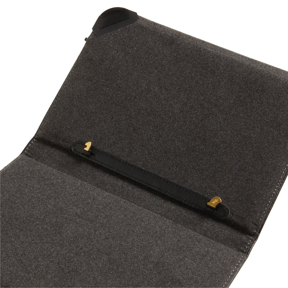
Step 6: Create the Back Inside Cover


The back inside cover will be where your kindle is attached to the light. I used High-density polyethylene (HDPE) sheet to make my back cover, but sturdy cardboard from a composition book or something similar would work just as well.
I followed this DIY Kindle Cover Instructable for the basic setup.
1) Follow the DIY Kindle Cover instructable through step one, concluding with felting the spine. Note, attach the spine felt ONLY to the front and back covers. Leave the portion that crosses the spine unattached to allow the book to open more naturally.
2) Make a template that is aproximately the same size as the inside cover of your book. I found that gently curved corners are much easier to attach felt to than square corners. My book has an internal dimension of 150 x 220 mm; attached is my template.
3) Glue the template to the backing material and cut it out.
4) Cut a piece of felt that has approximately 15 mm of overlap on all sides.
5) Use hot glue to fasten the felt to the backing. Trim the corners to make a nice rounded fit.
6) Place the clip support and light approximately where you would like them. Mark the locations. Be sure to allow enough clearance for the kindle to swing onto the lower clip. If the light is too close to the top of the kindle, it will be very difficult to attach the kindle to the clips as it will run into the light. NB! I wasn't thinking and centered my light on the backing rather than centering it with the Kindle screen. Note that it is off center by around 10 mm to the left.
7) Measure the dimensions of the light and support and trim away any felt and glue. Trim as close as possible to the light and support to allow for a nice finished look. Depending on the thickness of your felt, it may be neccesary to raise the clips slightly higher to ensure a good fit for the kindle ports. If this is necessary, make a spacer out of thin cardboard and fit it under the clip support. I needed to add a piece of cereal box cardboard to gain around .2 mm of height for my clips.
8) Cut holes for the wires from the clips to the switch and negative side of the light circuit.
9) Solder the positive (red) wire to pole [2] of the switch and the negative (black) wire to the negative side of the circuit
10) Test your lights. If something doesn't appear to work, check the following:
A) The clips are firmly seated in the Kindle
B) There is a good solder connection between the positive lead and the switch pole.
C) There is a good solder connection between the negative lead and the circuit.
11) Carefully align the light and support and fasten them down using hot glue. Tuck the felt in around the sides for a more finished look.
12) Insulate and secure the switch with a good blob of hot glue.
13) Attach the light hood using hot glue. This can be tricky and takes some experimenting to get right.
14) Decide where you would like the elastic band to rest over your Kindle. I set mine around 30 mm from the top and 30 mm in from the right.
15) Drill a small hole for each end with a sharp knife or 2 mm drill bit.
16) Cut a piece of elastic that is about twice as long as you need. Use a bent piece of wire or paper clip to fish the elastic band through the hole.
17) Glue the elastic band down to the backing leaving little to no slack in the band. Other than the bottom clip, this is the ONLY thing that will hold your kindle to the top clip so make it tight!
Attachments
Step 7: Create the Inside Front Cover and Finish


Create the inside front cover exactly the same way as the inside back cover. Add a few finishing touches and your K3 DIY light hack is complete.
1) Use the attached template to cut out a piece of thin cardboard.
2) Attach the felt using hot glue. Trim the corners to make a nice rounded and even fit.
3) Use hot glue to attach the inside cover to the front inside of the book.
4) Use hot glue to attach the inside back cover to the back of the book. I added an extra elastic band behind the back cover to help secure the front cover from flapping open.
6) Cut a small piece of 2.5 mm bass wood to cover the switch and glue it down.
7) Enjoy!
Please let me know what you think of this post. I'd love to see any improvements you all come up with. I am not completely satisfied with my solution and may re work a few elements. I'd love to incorporate some of the awesome ideas I see poke up on this site added to this project.
Attachments
Step 8: Final Thoughts
If I were to do this again, I would take the following into consideration:
A) The higher the lights are from the page, the easier the reading. Mount your lights as high as possible. There's a reason the official lighted cover has a pull out light. If someone can come up with a DIY hack similar to this, I'd love to see it.
B) push the lights back as far as you can into the hood. They can be very distracting and even blinding in a dark room when looked at directly. You're not going for a bright point of light, but rather a nicely scattered diffuse light over the entire face.
C) CENTER the light. It bothers me to no end that I didn't pay attention to the positioning of the light and didn't get it centered. But that's just a little obsessive behavior showing through.

Participated in the
3rd Epilog Challenge


