

Introduction: LDR Interfacing to Arduino
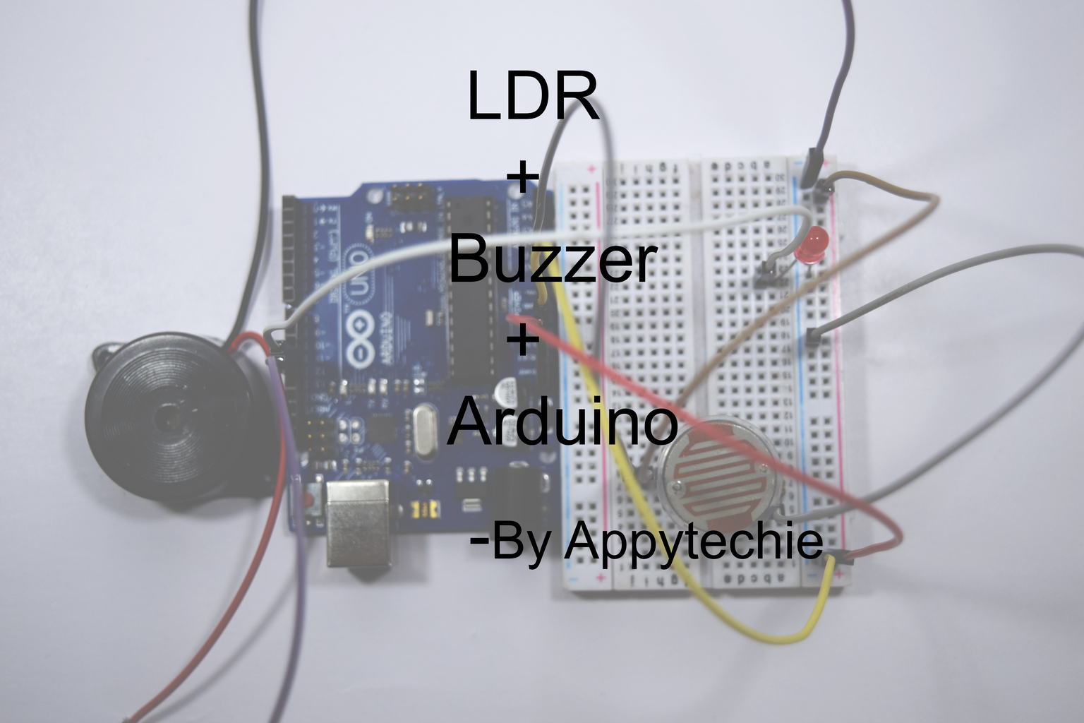


Hi, guys!! I'm Sridhar Hanrahan back another instructable dealing with the security system based on the light using an LDR sensor.This has a major application in bank security system and any light-based alarm system.seems interesting?Before getting into hardware interface let me explain to you what is a LDR ?.A light dependent resistance is a kind of resistor whose material is made up of high resistance material thus when the light falls on the sensor there is a kinetic energy happening inside the sensor causing the decrease in the resistance of the sensor.So having this little knowledge about this sensor let's get started to collect the electronics.
Step 1: Components Required:
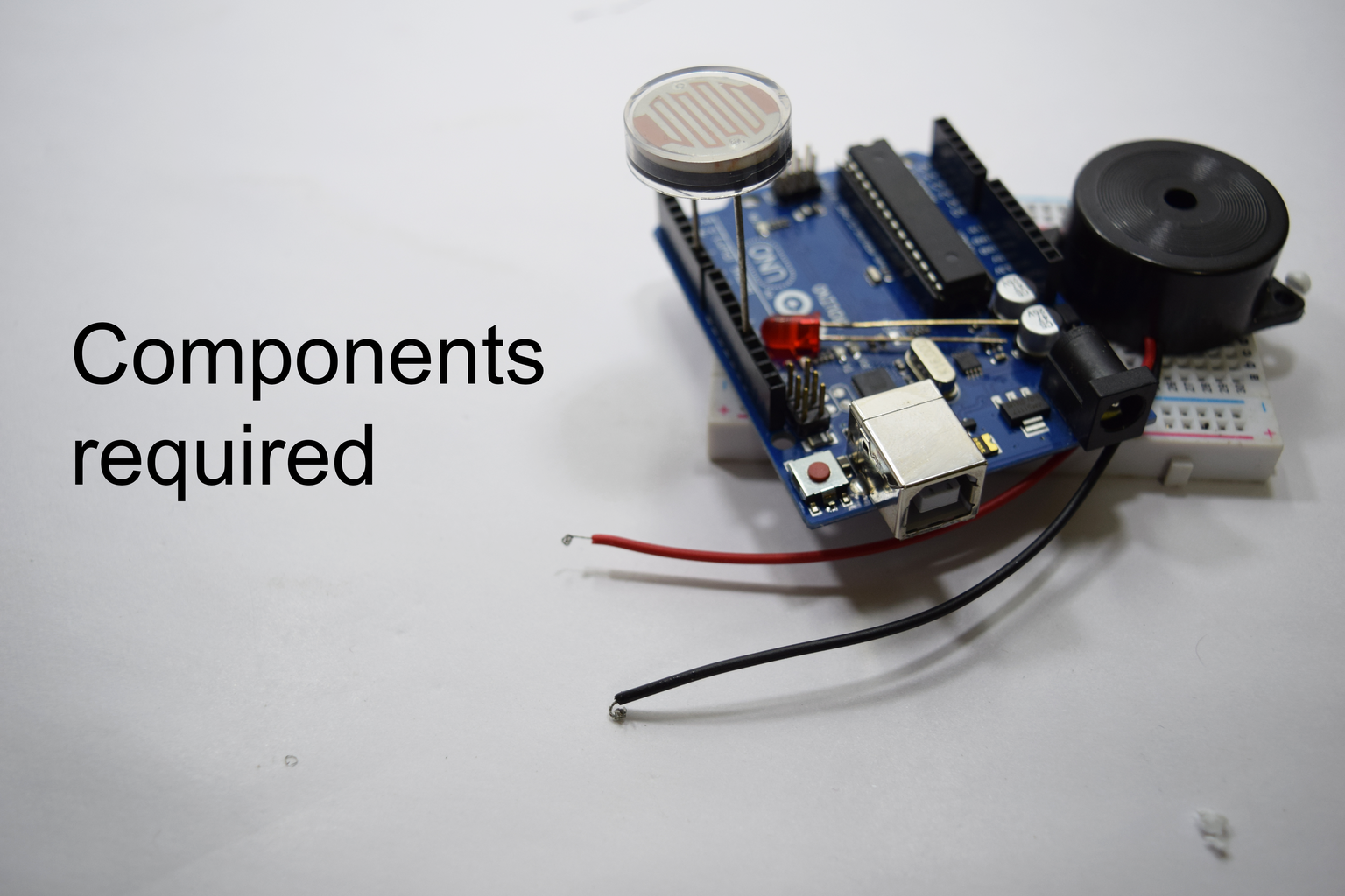


The component required for this projects are:
- Arduino Uno
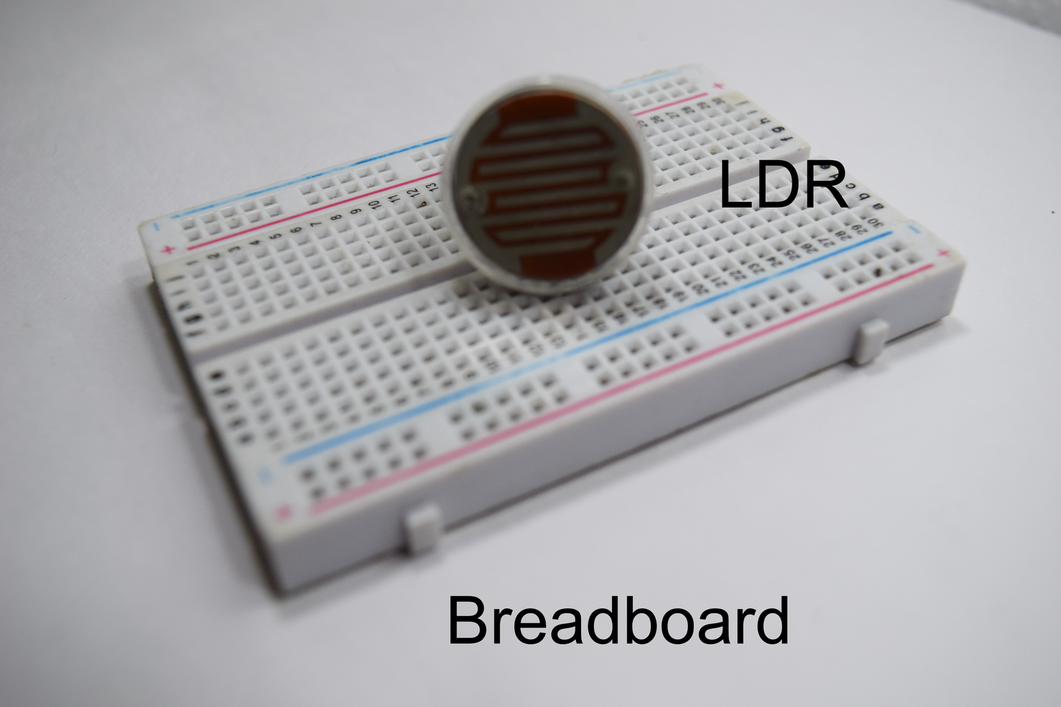
- Breadboard
- LDR
- Piezo buzzer
- A 220-ohm resistor
Let's start interfacing the Piezo buzzer in Arduino.
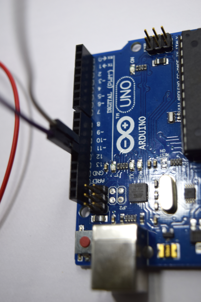
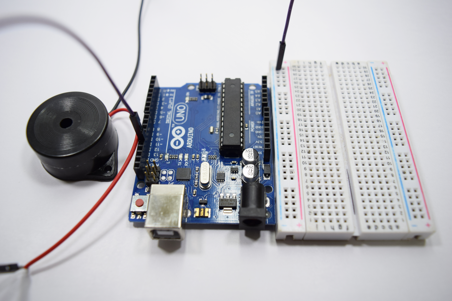
Step 2: Piezo Buzzer Interface:


The piezo buzzer contains two wire coming out of an enclosure.The red wire is called as positive or anode and the black wire is called as negative and cathode.
The connection of the piezo buzzer is followed:
- The black wire is connected to the negative railing of the breadboard.
- the red wire is connected to the digital pin 11.
Next,Let get start to connect the LED.
Step 3: LED Interface:

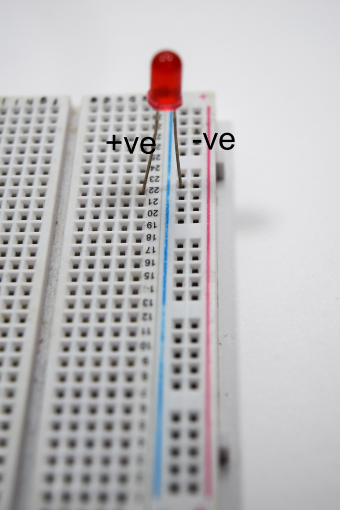
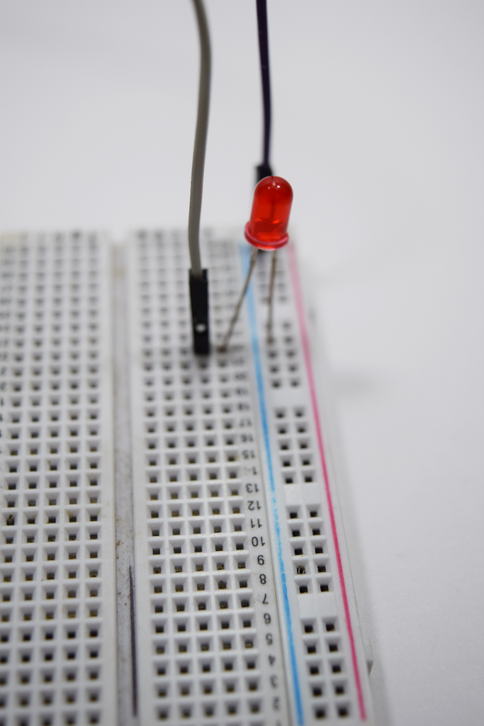
Light emitting diode is a two terminal semiconductor device.the two terminal vary in size, the longer leg is called as positive or anode whereas the shorter leg called as negative or cathode.
The connection of LED is as follows:
- The longer leg is connected to the digital pin 10.
- The shorter leg is connected to the negative railing of the breadboard.
Now let's connect the LDR.
Step 4: LDR Interface:
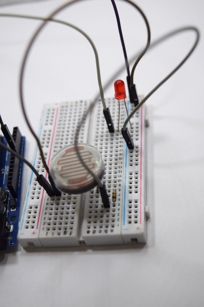
The connection of LDR is as follows:
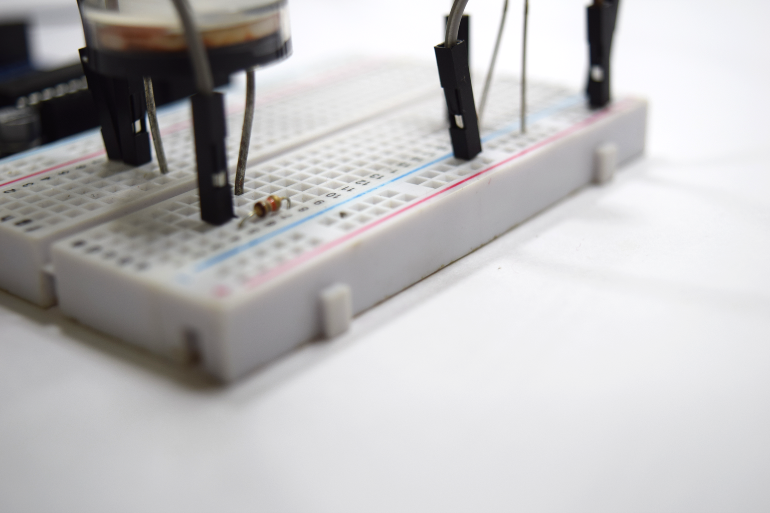
- The 220-ohm resistor is connected to either leg of the LDR.
- The leg to which the 220 ohms is connected is connected digital pin 13.
- The other leg of the LDR is connected to the Analog pin A0 of the Arduino.
Now let's get into coding
Step 5: Coding:
const int ledPin = 8;
const int buzzerPin = 9;
const int ldrPin = A0;
void setup () {
Serial.begin(9600);
pinMode(ledPin, OUTPUT);
pinMode(buzzerPin, OUTPUT);
pinMode(ldrPin, INPUT);
}
void loop() {
int ldrStatus = analogRead(ldrPin);
if (ldrStatus >= 400) {
tone(buzzerPin, 100);
digitalWrite(ledPin, HIGH);
delay(100);
noTone(buzzerPin);
digitalWrite(ledPin, LOW);
delay(100);
Serial.println(" ACTIVATED "); }
else {
noTone(buzzerPin);
digitalWrite(ledPin, LOW);
Serial.println(" DEACTIVATED");
}
}
If any peeps have difficulty in following the instructables please leave a comment below.
Thank you,

Participated in the
Makerspace Contest 2017


