

Introduction: LDR Sensor Module Interface With Arduino


This tutorial teaches the basics on using LDR Sensor Module.
Step 1: Introduction
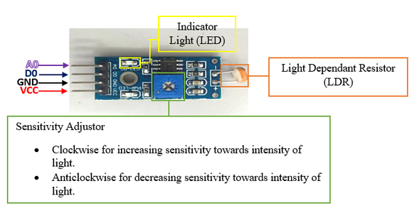
LDR sensor module is used to detect the intensity of light. It is associated with both analog output pin and digital output pin labelled as AO and DO respectively on the board. When there is light, the resistance of LDR will become low according to the intensity of light. The greater the intensity of light, the lower the resistance of LDR. The sensor has a potentiometer knob that can be adjusted to change the sensitivity of LDR towards light.
Specification:
- Input Voltage: DC 3.3V to 5V
- Output: Analog and Digital
- Sensitivity adjustable
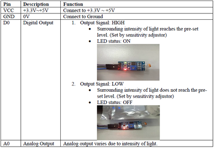
Step 2: Pin Definition
Step 3: Sample Hardware Installation (Analog Output)

Step 4: Sample Source Code
void setup()
{
Serial.begin(9600);
}
void loop()
{
unsigned int AnalogValue;
AnalogValue = analogRead(A0);
Serial.println(AnalogValue);
}
You can also download the sample source code attached below and upload it into Arduino. After that open "Serial Monitor" to see the result.

Step 5: Ways to Open "Serial Monitor"

First way to open "Serial Monitor".
Step 6: Ways to Open "Serial Monitor"

Second way to open "Serial Monitor".
Step 7: Result (1)

The reading shown on Serial Monitor when LDR sensor board is being exposed to sunlight.
Step 8: Result (2)

The reading shown on Serial Monitor when LDR sensor module is kept in a room with very little light /no light.


