

Introduction: LED Arduino Clock


After building my last project, I wanted to build something with an Arduino. Browsing Instructables for months I saw a LED Arduino Clock that I wanted to build. After some redesigns on my part, I set on my conquest to build this clock.
First and foremost, I want to give credit to Onyx Ibex, for all his help and for the original design of the LED clock.
INTRODUCTION:
The clock is a digital twist for a classic analog clock. There is an LED for each hour, minute, and second, all moving sequentially as the time changes. To keep things interesting, the hour "hand" LEDs cycle through a color fade so they are always changing.
The clock's electronics are created from 132 LEDs, an Arduino, and Real Time Clock breakout board. The clock also has roughly 6 feet of PVC tube, and 2 feet of ABS tube to form the "hands" for the clock, all mounted on a sheet of plywood painted black(in my case). The clock weighs about 10-12 pounds, certainly light enough to mount on a wall with a single nail.
Step 1: Gathering Materials

While there is a lot of materials used for this project, most of them are fairly inexpensive. The list of materials I used follows below:
Materials:
- 2' x 3' Sheet of 5/8" Plywood
- 2 feet of 2" OD ABS Pipe
- 3 feet of 1" OD PVC Pipe
- 3 feet of 3/4" OD PVC Pipe
- LOTS of Assorted Wires (roughly 200 feet, Any will work, I used what I had lying around)
- 12x0 3mm-5mm Solid Color LEDs (I used two separate colors, one for each section (minute, second))
- 12x 5mm RGB Common Anode LED's
- Spray paint (color of your choice)
- Light Diffusion Plastic (frosted plexiglass)
- Thin Metal Sheet
- 19x 100ohm Resistors.
- Lots of Solder
- Lots of Super Glue
- Real Time Clock (DS1307)
- Arduino Mega 2560 (Or a generic version, like I used)
- Header Jumper Pins
Tools:
- Saw (Table or Skill)
- Miter saw
- Drill
- Drill Bits
- PVC cutter
- Soldering Iron
- Wire Cutter
- Wire Spliter
- Needle Nosed Pliers
Step 2: Cutting Wooden Parts


EXPLANATION:
The first step of the project is to cut the wood parts out, including the mounting board, as well as the framing edges for the clock. I used a table saw, and I would recommend that, but if you are limited in your tools, a worm drive or skill saw should do the trick.
All the wooden pieces are cut from a 1/4" sheet of ABS plywood.
The mounting board is 23 3/4" squared. I would have made it 24" exactly, but I had a sheet already cut at 23 3/4", and I figured I could sacrifice the 1/4" to use the materials I already had.
The edges are 2 1/2" inches wide, with two boards being 23 3/4" long, and the other two being 23 1/4".
This cut list is as follows
- 1 - 23 3/4" x 23 3/4"
- 2 - 2 1/2" x 23 3/4"
- 2 - 2 1/2" x 23 1/4"
Step 3: Cutting Plastic Parts


EXPLANATION:
There are 3 different types of plastic parts for this project.
Each will need to be cut to size, and it is a time consuming part of the clock.
As you can probably figure out, you will need 12 hour hands, 60 minute hands, and 60 second hands.
- Hour Hands: 12 x 2" OD x 1 1/2" Tall
- Minute Hands: 60 x 1" OD x 3/4" Tall
- Second Hands: 60 x 3/4" OD x 3/4" Tall
To cut the PVC tubes, use a PVC cutter tool, and for the ABS, I use a Compound Miter Saw. When cutting the ABS, be careful to cut really slowly and leave the saw down until the blade stops spinning once the cut has been made. Having ABS splinter and shoot shards are you or others is not a fun experience. And remember to always use safety glasses.
Step 4: Arranging Plastic Parts


EXPLANATION:
For the plastic parts, I had to do some simple math to get the dimensions of the Minute hand PVC rings. I knew that the hour hand would fit easily in the middle of the minute hand ring with plenty of adjustment room. I also know that the second hand ring is smaller than the minute hand ring, so the second hand rings would not touch each other like the minute hand rings will. So I got the math for the minute hand rings and worried about the rest afterwards.
So the math begins:
The outside dimensions are 1 1/16", which converted to decimals is: 1.0625".
Because I am using a compass to draw the circle, I need to find the radius of the circle to set the compass correctly.
To get the radius of a diameter the formula is: Circumference / 3.14. Then Divide the diameter by 2 to get the radius.
So:
Circumference: 60" x 1.0625" = 63.75"
Diameter: 63.75" ÷ 3.14 = 20.30"
Radius: 20.30" ÷ 2 = 10.15" = 10 5/32"
INSTRUCTIONS:
After getting the radius, set the compass to that measurement, as close as possible, but accuracy is not critical.
Unfortunately I didn't take a photo of this step, but it's pretty self-explanatory. Mark the center of the board. The simplest way of doing this is to simply take each corner and draw a straight line connecting the opposite ones together, this will leave an X on the board, and the middle of the X where the lines intersect is the exact middle of the board.
Now using the compass, set the needle to the middle of the board and draw the circle for the minute hands. Do not use too much pressure of the line will show up through the paint.
After the line is drawn, start to arrange the PVC rings on the line. As I mentioned before it's not going to be precise, though as long as the circle looks like an even circle it will be alright and not lose any aesthetics.
Once the dry parts are arraigned, it's time to use the super glue and glue the rings down in place. The glue dries really fast and makes it easy to continue working on the next rings without worrying about them moving around while they are drying.
After the minute hands are glued into place, repeat the process for the second hand, then the hour hands. So to fix this, I placed the second hands in really close to the minute hands and I ignored the circle I drew for their placement.
Another note I should mention is to align the Hour hand rings to the X on the board that was drawn to find the middle. This ensures that the clock is going to be aligned vertically and horizontally with the corners of the board, as this clock is hung on the wall with the corners being the horizontal and vertically aligned.
Step 5: Painting


EXPLANATION:
Now for the simple part, painting the parts. I choose a black as I think the black looks good with the blue and white LEDs I choose for the minutes and seconds.
Up to this point, you should have all the plastic rings mounted, and all the sides of the clock cut out. Now it is time to paint the clock.
INSTRUCTIONS:
Simply put, paint the parts with some plastic safe spray paint. Be sure to paint all the inside and outside walls of the plastic rings. There is no need to paint to back of the clock, as it's going to be unseen, and it's harder to see your writing on the dark paint.
I would recomend dusting off the clock before painting it. I built mine in a wood shop and there was plenty of sawdust to build on my clock. So a simple air compressor took care of the problem right away,
Step 6: Soldering the Minute & Second Hand LEDs


EXPLANATION:
After many trial and error processes of soldering the LEDs, I found the easiest one is to solder a single wire to the cathode side of the LED, and shrink wrap it, to keep the pins from shorting out on each other. This method left the anode side pin open to solder directly to an un-insulated copper wire, saving a lot of time and materials.
INSTRUCTIONS:
First step is the cut a strand of wire, roughly 4 to 6 inches long, with one side stripped to roughly 1/4" Using a set of "Hobby Hands", carefully solder the exposed wire to the cathode side of the LED. Once the solder is complete, carefully cover it with some heat shrink tubing, or electrical tape, to prevent shorting out. Repeat the same process with the rest of the minute and second hand LEDs, but do not do it with the RGB LEDs just yet.
Step 7: Drilling LED Holes


EXPLANATION:
Now drill the holes for the minute and second hand LEDs to mount through on the clock. While making this, I chose not to drill the holes for the hour hands, as I wasn’t certain on how I was going to mount the hour hands LEDs. It's important for the holes drilled to be the correct size so the LEDs do not fall through the clock. Because I was using 3mm LEDs, if you use them as well, the same sized hole should apply for you as well. (It might be beneficial to double check beforehand though) The whole goal of sizing the holes is you want enough space for the pins to go through easily, but not too much space that the LED falls through the hole. So use the drill bit guide to find a correct size. Remember that the RGB LEDs are larger than the second and hour LEDs, and they have more pins/wires on the back, so they will need more room, thus a larger hole. Because we mount the hour LEDs on metal discs first, a large hole is all right.
INSTRUCTIONS:
Drill the holes in the middle of the plastic rings, being careful to center them as much as possible. If they are not perfectly centered, do not worry too much, it’s not as noticeable as I thought it would be. To avoid splintering of the wood, use a piece of scrap wood behind the clock to press the drill bit into. Though some splintering is probably bound to happen, it’s a good preventative measure, and it will help make the aesthetics of the back of the clock look better.
Step 8: Mounting the Minute & Second Hands LED


EXPLANATION:
The reason we used the sized drill bit that we did was to save us a lot of extra work for this step. The LEDs are pushed through the hole with the wires and pins going in first and sticking out through the back of the clock. This gives the LEDs a base to glue to the clock board and provides easy stability for the LEDs.
INSTRUCTIONS:
The steps are fairly simple for this part. Apply some glue to the bottom of the LEDs just above the pins and push the LEDs into the clock. To keep the LEDs in place while the glue dries, I used a small hobby clamp to hold the wire snug to the board and keep the LED in place. But, it is fats drying super glue and only take a few moments to dry, so you might find it un-necessary.
Note: To do this the easiest way, start with the minute hands before moving to the second hands. This allows you more space on the outside and less opportunity for wires to get in the way of your work.
Step 9: Wiring the Minute and Second Hand LED Grid


EXPLANATION:
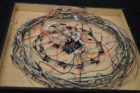
This has to be the hardest part of making this clock. Though it looks really complicated at first look, after the first couple rings around the clock it will make sense and you will see the pattern. The pattern is fairly simple, every 8 LEDs in a row are wired together for the Charlieplex grid.
To learn about
Charlieplexing, here is a great video that explains it. If you are not sure what Charlieplexing is, I would highly recommend watching it.
INSTRUCTIONS:
Begin by writing the LED number next to the LED. It helps to start writing the number of the LEDs on the board directly. This will give you a reference later on if you need it. You can also start to draw lines to group the LEDs together for the anodes. In the image I've included, they are all color coded.
Once all the LEDs are labeled and you are ready to connect them, begin by connecting the anodes together with a strip of exposed wire. I did not have any exposed wire on hand, so I made it myself. First, I cut the length of wire I needed, then I used a razor blade and carefully removed the plastic insulator. The problem was this left me with uncoiled wire, and it was a mess to work with. To solve this problem, put one end of the wire into the drill, and carefully hold the opposite side and use the drill to twist the wire until it's nice and tight.
After you have the wire ready, it's time to start soldering the pins to the wire. I did this by bending the outer ring of LEDs to the outside of the clock, with the wire pinned beneath them, and the opposite for the inner ring of the clock. Carefully solder each cathode LED pin to the exposed wires, moving around the clock until each and every LED's anode is soldered in the correct position.
That was the easy part, the hard part is soldering the cathode of the LEDs to the correct pin.
To do this, I worked in a counter clockwise direction and slowly added the LEDs to the wire as I went in circles. I used a length of wire the length of the circle, and started it on one LED, and slowly worked in a circle adding the LEDs to the wire as the diagram calls for.
Be sure to shrink wrap or electrical tape all the solders as to prevent short circuits.
Do this for both minute and second hands of the clock.
Refer to all the images above as examples.
Step 10: Soldering the Hour Hand LEDs


EXPLANATION:
This step requires a lot of practice with soldering, but even if you are not as experienced with soldering, it will start to come easier as you practice. Just have patience and it will work out.
This step is very similar to the earlier steps of soldering the LEDs, with the exception of there being 4 pins per LED versus the two pins for the second and minute LEDs
Be sure to check the manufactures specs for the LED if you purchased them from some place other than Adafruit. The schematics I am using is for the Adafruit ones specifically mentioned on the materials page.
If you are able to, use color coded wires for this step, it will save a lot of work and possible mistakes later on. If you are unable to use color coded wires, then tape a small piece of masking tape to the wire and label to color it is used for (R,G,B). For my clock, I was able to use color coded wires.
INSTRUCTIONS:
Simply solder a small length of wire to each pin on the LED. Use black for the common cathode, and use corresponding colors for the rest of the pins. Again, refer to the manufacturer's spec sheet if needed.
Once all 4 wires are soldered to the pins, cover every other pin with a shrink wrap tube of electrical tape to prevent shorts. You could technically cover 3 of the pins, or even all of the pins, but I believe it is a little over kill, as only the pins directly next to each other might touch.
I found it easiest to start on one side and slowly work to the other side as I soldered the pins. Doing all 12 matching colors before moving to the next color also seemed to work well for me.
Step 11: Cutting Hour Hand LED Diffusion Discs


EXPLANATION:
Because we are using a single LED to light up a large sized area, we use a diffusion plate to make the light a little more even. Though it is not 100 percent necessary, I believe it adds to the aesthetics of the clock and makes the hour hands look a lot cleaner.
I had a couple sheets of frosted plastic, much like Plexiglas, left over from an old light fixture long since removed. These were perfect for the covers of the hour hand rings.
I at first attempted to use the band saw and cut the rings out free handed, but the first one cracked nearly instantly, and the second attempt wasn't much better. This lead me to trying something else, a hole saw, which worked a lot more efficiently and neatly.
INSTRUCTIONS:
As we are using an Outside Diameter (OD) of 2 inches for the hour hand ring, we need to use the 2" hole-saw bit for "cutting" the plastic rings.
Before installing the hole-saw in the drill press, take out the center pilot hole of the hole saw. This will prevent the hole-saw from cutting a hole in the middle of the 2" diffusion disc.
Clamp down the plastic diffusion sheet down to the drill press. Be sure to use a piece of scrap wood underneath the plastic as to not damage the drill press.
Slowly cut the diffusion disc out of the sheet.
After all 12 discs are cut out, carefully break the melted plastic off the sides of the disc, to reveal a clean and perfectly round disc.
Sanding the discs also gives it a cleaner look, so I recommend that as well.
Step 12: Mounting the Hour Hand LEDs


EXPLANATION:
Similar to the same way we mounted the second and minute hand LEDs, we are going to mount the hour hand LEDs. Because we will attach the LEDs to the metal discs we made, mounting them is a lot easier than the minute and second hands were.
INSTRUCTIONS:
Take the metal discs me made, and drill a hole in the center of them, the same size as the LED, (probably 3 or 5mm).
Using super glue, glue the LED into the hole in the metal disc, refer to the images for a reference
Using a hot glue gun, apply some glue to the inside of the hour hand rings and insert the metal discs. Be sure to have all four wires from the LED fit through the hole in the clock so we can solder them.
Step 13: Assembling the Real Time Clock


EXPLANATION:
The RTC clock I used for this project does not come pre-assembled, and requires some basic soldering. I took these instructions directly from the Adafruit website. For more details visit the page here.
INSTRUCTIONS:
Place the circuit board in a vise so that you can easily work on it.
Begin by soldering a small bump onto the negative pad of the battery: this will make better contact!
Place the two 2.2K resistors, and the ceramic capacitor. They are symmetric so no need to worry about direction.
Then place the crystal (also symmetric), the battery holder (goes on so that the battery can slip in the side) and the RTC chip.
The RTC chip must be placed so that the notch/dot on the end match the silkscreen. Look at the photo on the left, the notch is pointing down. Double check this before soldering in the chip because its quite hard to undo!
To keep the battery holder from falling out, you may want to 'tack' solder it from the top.
Then flip over the board and solder all the pins.
Clip the leads of the resistors, crystal and capacitor short. If you'd like to use the header to plug the breakout board into something, place the header in a breadboard, long side down and place the board so that the short pins stick thru the pads.
Solder them in place.
Insert the battery so that the flat + side is UP. The battery will last for many years, 5 or more, so no need to ever remove or replace it.
Step 14: Soldering Header Pins


EXPLANATION:
Because the Arduino's inputs are very close together, it would take a lot of patience and time to get all the wires inserted into the Arduino correctly. To combat this issue, we are going to pre-solder jumper pins to the Arduino, making it a lot easier to connect them all to the Arduino when it is time. Do not worry about using any color coordination, unless you would like to. Simply numbering the pins should do the trick.
We also need to solder in the resistors now to keep the LEDs from being overloaded and burning out. Because we are using different colored LEDs we should technically be using different resistors for each color of LED. However, I decided to go the easy route and simple use 100ohm resistors for the minute and second hands. This works because each LED will get 2 resistors, the anode and cathode. 200ohm should be more than enough for the LEDs.
INSTRUCTIONS:
Simply take the ends of the wires that are going to be attached to the board, solder in a resistor, and wrap it with shrink wrap or electrical tape.
I found an easy way to soldering the resistors, and you can see them in the example photos.
Be sure to label all wires with the correct number, so you can plug them into the Arduino in the next step.
Step 15: Connecting It All Together

EXPLANATION:
Now is the fun part, seeing the clock come together. All the pins should be numbered, and ready to attach to the Arduino. If not, then follow the list below to number the pins correctly.
- 5 – Red Hour Pin
- 6 – Green Hour Pin
- 7 – Blue Hour Pin
- 12 – Hour 1
- 13 – Hour 2
- 14 – Hour 3
- 15 – Hour 4
- 16 – Hour 5
- 17 – Hour 6
- 22 – Hour 7
- 23 – Hour 8
- 24 – Hour 9
- 25 – Hour 10
- 26 – Hour 11
- 27 – Hour 12
- 28 – 36 Second Pins
- 37 – 45 Minute Pins
- 20 – RTC Clock (SDA)
- 21 – RTC Clock (SCL)
- GRN – RTC Clock (GRN)
- 5V – RTC Clock (5v)
INSTRUCTIONS:
In whatever order you deem appropriate, start plugging in the pins for the Arduino board. Hopefully up to this point, you have numbered your pins and you know which one goes where, if not, refer to the wiring diagram from earlier on, and use the list above.
Once all the wires are connected, use a small screw to mount the Arduino and RTC to the back of the clock to keep them in place and stable. Be sure not to over tighten the screws as it will probably damage the circuit boards.
Step 16: Setting the Time.


EXPLANATION:
Before the clock will work, we need to set the time on the clock. This is the first step with programming the Arduino, so it might become a little confusing if you have no experience with programming Arduino. If you need some help, here is an excellent tutorial to get you started.
Here is the documentation for the DS1307 RTC, download the RTClib-master.zip file and add it to your Arduino libraries.
Inside of the ZIP folder, there is instructions on how to set the clock. It's pretty self-explanatory, but if you have any questions, feel free to keep reading on.
INSTRUCTIONS:
Download the Arduino code for setting the clock. While you can find a code similar to this one inside the RTClib-master.zip library, I’ve included a simpler one with the only function being setting the clock, and checking the time on the serial monitor.
You’ll also need to download and install Arduino, either as a regular program, or as a portable program.
Once you’ve downloaded and installed Arduino, it is time to upload the clock code to set the RTC. To do this simply download the code, and open it up in Arduino, and click the top buttons to verify the code, and upload the code.
Your clock should be set now. If you want to verify that the correct time is displayed, open the serial monitor by pressing Ctrl+Shift+M. Make sure the baud rate is set to “57600”, if it is not, then set it by clicking the numbers in the bottom right corner of the serial monitor and select “57600”.
If you are having problems setting the time, I’ve included some images to help you through the process.
Attachments

Step 17: Uploading the Arduino Clock Code / Testing the Clock

EXPLANATION:
After all this work, it is finally time to connect it all together and test the LEDs. The Clock code has a debug feature built in to run the LEDs though a test cycle to ensure they are all working correctly. It will slowly cycle through the LEDs in order.
Hopefully your LEDs are all soldered correctly, but if not, then now is the time to repair any that might be defective.
Up to this point everything should be attached to the clock with the exception of the hour hand diffusion discs, and the side trim of the clock.
INSTRUCTIONS:
Similar to what we did with the program to set the RTC, we are going to do this with the main clock program as well. So download the program, and open it in Arduino, then install it to the Arduino.
When power is first applied to the Arduino, it should take a moment, then cycle the LEDs through a testing phase. This will show each LED powered on, one after the other. So pay attention to each LED and make sure they all turn on, and in the correct order.
After the test cycle is complete, the clock should show the proper time. If you have the pins in a different configuration, then they will not work properly. If this is the case, simple change the pin order in the top of the code, until you get the right code.
For example, if your clock runs in the wrong direction, then we are going to reverse the pin order, essentially mirroring the clock and making it run in the correct direction.
Attachments
Step 18: Attaching the Sides / Hangers


EXPLANATION:
Up to this point, we should have a working clock, one that works very well, but could use some cleaning up, but working non-the-less.
To do this step, we simple glue and tack in the sides we cut out earlier to frame the edges of the clock.
They should be painted and ready to go all ready, so it's just a matter of applying some wood glue and stapling them to the back edges of the clock.
I used an air compressor and nail gun, though simple nails and a hammer would suffice. Be sure to use plenty of glue.
For the Hangers, I simply used some eye-hooks, and a small strand up wire.
INSTRUCTIONS:
After applying glue to the edge of the clock's back, carefully attach the longest board to the edge with the nails.
This will set the edges to align the shorter boards to, ensuring a flush seam.
After all boards are attached, use the nails to tack the edge boards together to give it more stability.
Be sure to wipe away any excessive glue that might have squeezed out of the edges.
Once the edges are dry and stable, insert two eye-hooks, one for each side of the top of the clock.
After the eye-hooks are inserted, use a heavy gauge wire to string between the eye-hooks to give you a place to hang the clock from.
Step 19: Attaching the Hour LED Diffusion Plates


EXPLANATION:
Before you glue on the diffusion discs, ensure that the hour LEDs are working properly. If they are indeed working properly, then it is time to glue on the diffusion discs and finish the clock.
INSTRUCTIONS:
Using super glue, glue the diffusion discs onto the hour rings of the clock. Use plenty of super glue so the discs do not fall off after a short amount of time.
Be sure to center the discs onto the hour rings, or they will not look as good.
Step 20: End Notes
At the time of writing this, I am in the process of programing some “events” on my clock. For example, every 5 minutes, I would like to make the clock’s hours cycle through colors much like a turning wheel, just for a bit of flavor. As the clock is programmed with Arduino, there is many other options and ideas we can add to the clock.
When I get a different stable code, I will upload it as well, so check back from time to time, or subscribe to have automatic updates.

Participated in the
Full Spectrum Laser Contest 2016


