

Introduction: LED Etch-a-Sketch (Full Instructable)


I would like to state that during the course of this instructable I assume that the reader has a basic understanding of using AVR and programming in C.
Step 1: Electronic Components
Logic:
- ATmega328p
- 16MHz Clock Crystal
- 22pF Capacitor (2x)
- 0.1uF Capacitor
- 10k Ohm Resistor
- 8x8 Common Cathode LED Matrix (4x) (Sparkfun #COM-00682)
- 74HC595 8-bit Shift Register (4x)
- ULN2803 Darlington Driver (4x)
- 100 Ohm Resistor (32x)
- Tilt Switch (2x) (Sparkfun #SEN-10289)
- 10k Ohm Potentiometer (2x)
- MintyBoost Kit (Sparkfun #KIT-10094)
- Male Right-Angle Breakaway Headers (1x) (Digikey #A34346-40-ND)
- Female Right Angle Receptacle (4x) (Digikey #A35044-ND)
- 14-Pin Ribbon Cable 6" (Digikey #A4AAH-1406M-ND)
- Female Straight Receptacle (8x) (Digikey #A26422-ND)
- 2x3-Pin Male Header
- 14-Pin Ribbon Cable 4" (Dgikey #360-2433-ND)
Step 2: Tools


You will need the tools found in most electronics toolboxes, like a soldering iron, needle nose pliers, and wire cutters. You will also need lots of spare wire and wire strippers.
To program the ATmega you need an AVR programmer. I found the USBtinyISP from Adafuit to be an inexpensive and quality solution to other expensive programmers out there.
Step 3: Designing the Logic

The logic portion, as I'll call it, contains the ATmega328p and all components necessary to its operation. The design is nothing that should be unfamiliar to those who have used an ATmega controller before. About the most exotic thing here is the use of an external oscillator with requires the fuses on the microcontroller to be adjusted. In order to figure out the proper fuse settings I used this handy calculator: http://www.engbedded.com/fusecalc/ by Engbedded. Otherwise, you have a 10k Ohm resistor on the reset pin and a decoupling capacitor between the supply voltage and ground.
We'll talk about pin connections and assignments to control the driver circuitry later on.
Step 4: Designing the Drivers


At first thought, driving an LED matrix is a simple endeavor. Simply hook the anodes to one set of microcontroller (uC) pins and the cathodes to another and there you go, right? Well that would be nice but it's a big problem for two reasons. One, the if we wanted to expand this to large matrices we would quickly run out of pins. Second, when multiple LEDs are lit up at the same time with set-up we run the risk of the current draw on the uC pins being so high that we damage unit. So how do we get around these problems? Which the use of extra integrated circuits and little trick in the software.
Here we'll be discussing how hardware helps us solve the above problems and we'll discuss the software trick a little later on.
So I know that my LED Etch-a-Sketch will require four 8x8 LED matrices. That means I have 256 LEDs that need to be individually addressed. That's quite a bit. So how to we do it? Well first we need to understand how the LED matrix works. The particular matrix I used is called a common cathode LED matrix. It may make understanding what this means if I add a little to the name. Lets call it a common cathode row LED. So now we know that all the cathodes in each row are on the same line (see the first image). This allows us to control a single LED by simply supplying a positive voltage to the column and ground to the row corresponding to the LED we want lit. For example if we want to light the LED at (4,4) we would apply ground to row 4 and a positive voltage to column 4 as seen in the second image. From this we know we need so control all the column lines. But what about the row lines? If we just tied all these to ground then we would never be able to have different LEDs lit on each row. This tells us that we also need to control the row lines.
We'll look at the entire 16x16 display as an 8x32 display as that's how it will be wired up. You can see this in the third image above. To control a display of this type we will need to control 32 lines for the columns and 8 for the rows. Row control is no problem; we have eight pins available to us on the uC. The only thing to be concerned about is how to sink the current without damaging the uC. I'll address that in a second. But first let's figure out how we are going to control 32 lines when we clearly don't have 32 uC pins available.
The trick is to use the handy 74HC595 serial-in parallel-out 8-bit shift register, or, as I'll refer to it from now on, the 595. This IC allows us to serially send a byte of data to be stored in the register and then when signaled that data will appear in parallel (at the same time) on the output pins. It also allows for multiple 595s to be cascaded or connected together to accept an input larger than 8-bits. I'm not going to send time discussing the theory behind this device, as there are many resources available online that will do it. But at this point I'm sure you can guess where we are going with this. If we cascade four of these 595s together we can serially control all 32 column lines with just a few uC pins.
Let's quickly get back to the rows. As mentioned above we need to be careful not to send all the current through the uC to ground so we'll use a ULN2803 at each matrix. This will allow us to control the row lines while at the same time sinking the current.
We'll talk about how these ICs is used in conjunction with the software to successfully control the the LED matrices. But first let's get everything wired up properly.
Step 5: Combining the Logic and the Driver


This step is the simple matter of connecting everything together. Unfortunately doing this on bread boards is quite messy as you can see in the first photo. Alas, it had to be done, at least in my opinion.
First off, let's go ahead and get the ULN2803s hooked up as it about as simple as it gets. If we look at the datasheet for this IC we see it has 18 pins, 8 will be for out control lines from the uC, another 8 will be connected to the rows of the LED matrices, one pin is ground, and one is common which we will be leaving disconnected here. The inputs 1B - 8B (pins 1-8) will be connected to the Port D of our ATmega328p in the order where PD0 connects to 1B and so on. The outputs 1C - 8C (pins 18-11) will be connected to the rows of the LED matrices where 1C connects to row one and so on. Lastly, the ground pin connects to ground. You can see this in the schematic above. (You're probably going to want to view this full size).
Here's where it gets interesting, because not do the 595s need to connect to the uC, but they also need to connect to each other. First let's get the connection to the uC squared away. In order to interface with the 595s we will be using the SPI bus on the ATmega328p. This involves the use of specials pins on the uC labeled SCK (PB5), MISO (PB4), MOSI (PB3), and SS (PB2). The SCK is the serial clock; MOSI stands for master output slave input, MISO stands for master input slave output; and SS the slave select. Since our ATmega328p will be the master and will only be outputting data we will not use the MISO pin. I'm going to go into the details of the SPI bus because quite frankly I don't know that much, but understanding all its complexities is not necessary to completing this project. I will, however, discuss what is going one here when we get to the software step. For now, connect the SCK (PB5) from the uC to SRCLK (pin 11) and SS (PB2) from the uC to RCLK (pin 12) for each 595. Then connect MOSI (PB3) from the uC to SER (pin 14) of the first display's 595 as shown in the schematic. We can cascade the 595s by connecting the QH' (pin 9) of the first 595 to the SER pin of the second and continue as in the schematic. Next you need to connect the OE (pin 13) to ground to enable the output. And the SRCLR (pin 10) to positive supply voltage so that we never clear the serial data. To connect the 595s to the LED matrices, the pins go in the opposite order that you expect. Here you want to connect QA to the that controls column 8, QB the pin that controls column 7 and so on. We're doing this because the most significant bit (MSB) is on the left. I'll address this more when we talk about the software.
A note, the datasheet for the LED matrices are not very clear on what pins are what. The last image on this step, as bad as my drawing is, shows the pinouts and connection for the components. There is a YS printed on one side of of the LED matrices to indicate the top direction and the YS on drawing should match it.
Step 6: The Software


This is where it all comes together. I'm going to try to talk about all the important parts of the code briefly. The code is attached and commented so that you can see it in its entirety.
As with all C programs we first have out includes. You'll need io.h and interrupt.h for this project. Next, I defined some symbols so that it would be easier to work with them in the program. I think it's easier to know what I'm doing when I use SPI_PORT instead of PORTB. Then we have the function prototypes; nothing too special here. Lastly in this section we have our global variable definitions. There are a few I would like to bring your attention to.
int currentRow = 0;
unsigned int cRow = 0, cCol = 0;
int rowRead, colRead, factor;
int soft_prescaler = 0;
unsigned long drawing[8] = {0};
The currentRow variable, as its name suggests, holds the value of the current row we are displaying. You'll see exactly what this is used for a bit later. cRow and cCol hold the values of the cursor's row and column. rowRead and colRead hold the values of the ADC reading taken from the pots. These will be used in calculating the value of the cRow and cCol variables. The soft_prescaler is used to further divide the clock with the software; we'll discuss it later. Finally, the most important variable is an array of unsigned long ints called drawing. You'll notice this array contains eight elements- one for each row. This holds the 32-bits that control the LEDs for each column.
Now let's move on to some functions. We'll start with the main function. After performing the set up of the Timer, SPI, and the inputs and outputs we enter the main program loop. The first think inside this loop is an if statement.
if(counter < CYCLES)
{
rowReadings[counter] = Analog_Read(PC4);
colReadings[counter] = Analog_Read(PC5);
counter++;
}
This is simply taking a sampling of ADC readings over so many CYCLES. This is used to compute an average of the ADC reading and prevents problems with the drawing. Entering the else will show how this is done.
else
{
//Average all Row and Col ADC readings
colRead = CycAvg(colReadings);
rowRead = CycAvg(rowReadings);
counter = 0;
After we've got a sampling of ADC values for the row and columns we can average them using the CycAvg function. This is just a generic averaging function that sums up the values and then divides by the total number of values. I'm not going to talk about it here as you can find it in the code. Well, now that we have the ADC readings we want from the pots, we need to convert this to a row and column number so we can place the cursor there. This is handled next.
if(colRead / DIVISOR != cCol && colRead / DIVISOR < DIMENSION)
{
cCol = colRead / DIVISOR;
}
The cursor column value is straight forward to calculate. We check that the new value is not the same as the old value (because there would be no need to recalculate it) and we make sure that the cursor does not go beyond our 16x16 drawing surface. Then we assign the value of the ADC reading divided by the value of DIVISOR. DIVISOR is just the maximum value of the ADC divided by the dimensions of the display (1024/16=64, so every 64 we are on a different row or column). The cursor row value is a bit more complicated.
if(rowRead / DIVISOR != cRow && rowRead / DIVISOR < DIMENSION)
{
if(rowRead / DIVISOR >= 8)
{
cRow = rowRead / DIVISOR - 8;
factor = 0;
}
else
{
cRow = rowRead / DIVISOR;
factor = 16;
}
}
So what's with this extra if statement? This goes back to how we wired up the displays as if it were actually a 8x32 display instead of a 16x16. The first 16 bits of our drawing variable correspond to the first 16 columns of the 8x32 display. The remaining 16 bits correspond to the second 16 columns. When we make the display 16x16 we are moving the last 16 columns and placing them below the firs 16 columns artificially creating 8 more rows. If we want to calculate the cursor row in the same way as we did the cursor column we may end up with a value more than 8. Remember we only have eight rows since our display is technically 8x32 so this creates a problem. So if the result of the division of the ADC by DIVISOR is greater than 8 we need to subtract 8 and use that as the row, otherwise we can just take the result as is. We also need to keep track of whether or not the drawing is happening in the first 16 columns (rows 9-16) or the last 16 columns (rows 1-8). That's where the factor variable comes in. This should make more sense when we actually assign a value to the drawing variable next.
drawing[cRow] |= (0x80000000 >> (cCol + factor));
Quite a bit is done here. First, we'll give the array our cursor's column as an index and then we'll bit-wise OR this with the next part. We're using bit-wise OR here because we want to keep all the bits that have already set where they are and only set the one corresponding to the cursor's location. On the right side of the operator, we're shifting a single bit to it's proper location. For example, let's say the value of cCol is 4 and cRow is 5. In this scenario, drawing[5] |= (0x80000000 >> (4 + 16)) = 0b0000000000000000|0001000000000000. To better clarify what bits correspond to what, the 16 most significant bits correspond to the columns of rows 1-8, the 16 least significant bits correspond to rows 9-16.
The last part of this loop checks if both tilt switches are closed at the same time. It's very simple and relies on fact that there is a high probability that the two switches will close at the same time when the device is shaken.
//Clear Screen if tilt sensors are tripped.
if(bit_is_clear(PINC,0) && bit_is_clear(PINC, 1))
{
clrscr();
}
Now that the drawing is done we need to get it to the display. This is taken care of by the Interrupt Service Routine (ISR) that is triggered on every timer overflow. Let's look at.
ISR(TIMER0_OVF_vect)
{
soft_prescaler++;
if(soft_prescaler == SFT_PRESCAL_MAX)
{
currentRow = (currentRow + 1) % 8;
//Transmit Data on SPI
SPI_Transmit(drawing[currentRow]);
PORTD = (1 << currentRow);
soft_prescaler = 0;
}
}
The first thing we do in the ISR is increment the soft prescaler. The soft prescaler basically allows us make the time each row is displayed something other than what we can with the ATmega's hardware prescaler. If you look at the Timer_Init() function you see we prescale the clock by 8 with the hardware. So our 16 MHz clock becomes 2MHz. With a soft prescaler with a maximum value of 15 we can bring the time each row is displayed down to about 133 kHz. This wouldn't be possible with a hardware prescaler. Anyway, let's move on.
When we do reach the soft prescaler max we first decide what row we want to display. Each time the interrupt fires it will display only a single row. This happens so fast that our eyes cannot see the changes and so the image looks solid. This technique is called multiplexing and it used for lots and lots of applications. To set the current row we will first add one to it to increase the row then mod it by 8 so that the value will always be somewhere between 0-7. Then we send the drawing for the current row to the SPI_transmitt function to transmit the data to the 595s. After that we set one of the Port D pins high corresponding to the current row. Recall these pins are connected to the ULN2803s. Finally, we reset the soft prescaler to zero and do it all over again.
That's pretty much it. All the other functions are just supporting these two. Definitely check them out in the attached code.
Attachments

Step 7: Designing the Printed Circuit Boards


I originally wanted to put everything on a single board, however, after making a schematic in Eagle I realized that the board would exceed the maximum dimensions allowed in the free version so I decided to break them up into smaller parts. The logic board, as I call it, holds everything that has to do with the operation of the ATmega328p. It's nothing too special.
The boards for the drivers, however, ended up being pretty handy. Since each board contains everything necessary to drive a single LED matrix they can be used beyond just this project. I ended up getting extra boards made and I could use them to create any type of display.
The Eagle files are available for download so you can run them through any CAM script your board house wants to use. I had the boards for this project made with BatchPCB. They're a service of Sparkfun and and I was really pleased with the results, though the lead time was substantial. I recently used IteadStudio's PCB service and was very happy with it. Cheap and relatively quick for high quality PCBs. These are just two suggestions if you're new to fabricating PCBs. Otherwise you can just use your favorite board house.
Attachments
Step 8: Assembling the Device

Assembly is pretty straight forward. A lot of soldering, but what did you expect. I'm not going to instruct you how to solder here. If you don't know check out the many instructables in how to solder.
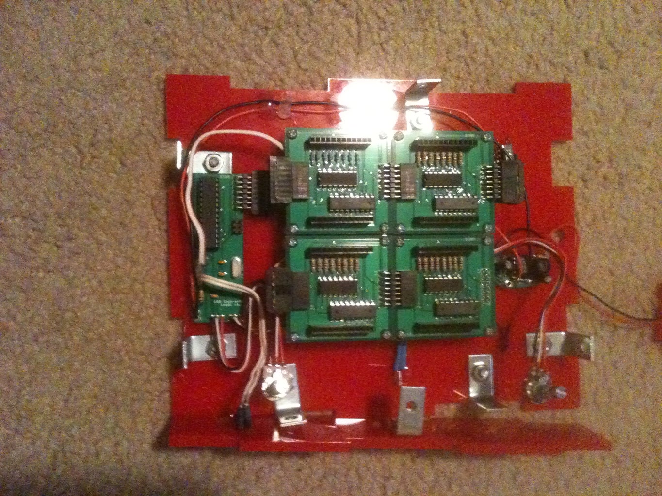
After assembling all the boards you're going to want to figure out what you eventually want to do with it. This way you can add appropriate lengths of wires for the pots and tilt switches. As you can see from the image, my enclosure required decently long wires to place the pots and tilt switches in the appropriate location.
A note on tilt switch placement: you need to figure out a location for your tilt switches that best fit your use. For me, I wanted to be able to use the device while it is laying on a flat surface and while being held vertically, about perpendicular to the ground. To that end, I placed once switch on the side of the enclosure with the leads pointed up so that when the device is laying on a flat surface that switch is always open and the screen will never clear. The other switch I placed on the bottom (the red part your seeing in the image above) with the leads pointed towards the top, that way when the device is held vertically the switch will be open.
For assembling the MIntyBoost I refer you to https://www.instructables.com/id/MintyBoost!---Small-battery-powered-USB-charger/
While we're on the topic you may be curious as to why I'm using a MintyBoost to supply the power to the project. I answer is quite simply that the MintyBoost is a nifty little device to step-up voltage. I designed the device to run off 5V and for the longest time I was planning on just using a 5V power supply that plus into a wall. I really didn't like that idea because I didn't think the LED Etch-a-Sketch would be much fun if it had to be plugged into a wall all the time. I looked some other step-up converters but didn't find any that would be able to supply the current I needed. Then I came across the MintyBoost. It can give me 5V and high current, it's small, and one less thing I had to worry about designing and building.
Step 9: Enclosing and Finalizing


At this point it's kind of up to you to do what you want with it. I decided to make an enclosure out of laser cut acrylic, however you can do whatever you want to enclose your device. I recommend picking up some knobs (Sparkfun #COM-10002) and painting them white, because for whatever reason plain white buttons seem impossible to find.
Get creative and have fun here!
Step 10: Have Fun
And we're done! I know that was a lot, but I hope you stuck it out long enough to learn something. Thanks for reading!

Participated in the
Hurricane Lasers Contest


