

Introduction: LEGO T-Intersection LED Traffic Light

Video not playing? See it on YouTube: http://www.youtube.com/watch?v=q0tiiWwC6Zo
Background
Every Christmas we set up a large LEGO train layout in a section of the living room. This year, I ended up winning an eBay auction for a number of older-model LEGO road plates, one of which included a T-intersection. At about the same time, I saw a web magazine article on how to get started programming an Arduino embedded microcontroller. I'm a computer programmer by trade.
Inspiration
It seemed obvious to me at this point that a perfect project would be to create an LED traffic light out of LEGO bricks, some LEDs and resistors and an Arduino Nano controller. The T-Intersection became the center-piece of the layout. This Instructable will lead you through building the traffic light, as well as illustrate how the Arduino program works.
Take Two
This is my second attempt at building the traffic light. On the first attempt, my 9-year old son helped me. Being slightly impatient, as 9-year-olds are apt to be, I was left with no time to take detailed photographs. The LEDs I used, found in my parts bin, were also extremely dim: bright at night, but invisible in the day.
With this second attempt, I obtained much brighter LEDs from a string of LED Christmas Tree lights that only half lit up. I also took very detailed close-up photographs with a brand new Sony DSC-TX5 digital camera that can close focus down to 1cm. I've annotated many of the photos.
Alternates
You can choose to build this Instructable as presented or just use it for inspiration for your own creation. I realize that LEGO T-intersection road plates have long since been discontinued and are hard to come by now. Cross-intersections are all that are available in LEGO stores now. You might choose to build a fourth light. I've supplied an alternate program that should drive a cross-intersection with four advance green-lights. It should work, but since I was testing the program only on my T-intersection, it might not work perfectly. You'll need more LEGO bricks and LEDs to build such a light.
Step 1: Part List
Electronic parts for this Instructable,
- 4-green LEDs, 20,000mcd
- 3-yellow LEDs, 20,000mcd
- 3-red LEDs, 20,000mcd
- 2-220& ¼-watt resistors
- 2-150Ω ¼-watt resistors
- 1-Arduino Nano micro-controller
- 1-5 pin male header
- 2-4 pin male headers
- 2-2x15 long female headers
- 1-2x6 long female header
- 1-50 foot spool Kynar #30AWG wire
- 36-2x2 round grey bricks
- 3-1x2 grey brick
- 3-1x2 modified grey technic brick with hole
- 12-1x1 round grey brick with holes in the stud
- 3-2x2 round grey tile
- 1-1x2 yellow plate
- 1-1x3 yellow plate
- 1-1x1 yellow tile
- 3-1x4 yellow tiles
- 2-1x4 yellow plates
- 13-yellow head light bricks
- 1-T-interesection road plate
- :#14AWG wire-stripper
- #30-guage wire-stripper2-pliers
- 1-utility knife2-wires with alligator clips at each end for testing LEDs
- 1-hot glue gun
- 25 Watt soldering iron
- fine rosin core solder
- wire cutters/nippers
- heat shrink tubing
- heat shrink gun (or use heat from a soldering iron)
Should you choose to build the alternate model, this is my best guess at the parts that are required.
Electronic Parts:
- 8-green LEDs, 20,000mcd
- 4-yellow LEDs, 20,000mcd
- 4-red LEDs, 20,000mcd
- 2-220& ¼-watt resistors
- 2-150Ω ¼-watt resistors
- 1-Arduino Nano micro-controller
- 4-5 pin male headers
- 2-2x15 long female headers
- 2-2x6 long female header
- 1-50 foot spool Kynar #30AWG wire
- 48-2x2 round grey bricks
- 4-1x2 grey brick
- 4-1x2 modified grey technic brick with hole
- 16-1x1 round grey brick with holes in the stud
- 4-2x2 round grey tile
- 4-1x2 yellow plate
- 4-1x3 yellow plate
- 4-1x1 yellow tile
- 4-1x4 yellow tiles
- 13-yellow head light bricks
- 1-Cross-interesection road plate
Step 2: Testing LEDs From a String of Christmas Tree Lights

- 4-green
- 3-yellow
- 3-red
You can opt to purchase LEDs if you wish. You'll want LEDs that are rated at 20,000mcd (millicandela). That's bright enough to see them in sunlight. If you buy LEDs or have some on hand, you can skip straight ahead to step 7.
This, up to step 6, are all about extracting an LED from an individual Christmas tree bulb.
First cut an LED from the string of lights, strip the ends of the wire with a #14AWG (American Wire Gauge) wire-stripper and test the LED. Do this for each LED. You don't want to bother breaking into a light only to find out later it was burnt out. LEDs last a long time, but they can burn out.
I like to fiddle with electronic circuits from time to time, so long ago I built myself a dual-voltage, dual-polarity power supply and incorporated some other features into it, such as some fixed rate frequencies, a variable-rate frequency generator, and an LED tester. That's what you're looking at in the image.
The LED tester is simply nothing more than a 1KΩ (kilo-ohm) resistor connected to the +5-volt portion of the power supply. The LED is then connected to the other end of the resistor resistor and the ground of the power supply.
You can make your own LED tester from a 9V battery and a 1KΩ resistor. Tape one lead of the resistor to the positive (+) terminal of the battery. Then briefly touch one lead of the LED to the other lead of the resistor and touch the second lead of the LED to the ground (-) terminal of the battery.
LEDs light in only one direction. If it doesn't light, swap the leads around and try again. If it still doesn't light, toss it out and try another LED.
Step 3: Breaking Into a Christmas Tree Light


Wear safety goggles!
You don't want any stray crystal plastic flying into your eye.
- Grasp the green base of the LED light with one set of pliers.
- Grasp the plastic crystal tip of the light with another set of pliers.
- Bend one set of pliers away from the other until you hear the crystal plastic snap and fall off. Be careful, as you could possibly damage the the LED in the process.
Step 4: Cutting the LED Out of the Christmas Tree Light


Now that we have the LED exposed, we have to get it out of the moulded plastic base that it's trapped within.
Wear safety goggles!
You don't want a bit of knife blade breaking off and flying into your eye. Nor do you want any stray crystal plastic trapped in the base of the light to fly into your eye.
Grasp the base of the light with pliers. Using a utility knife, begin to gently cut into the plastic base. It's quite soft. Be gentle, and work your way around the light. I used the little groove moulded into the light to guide the knife.
The plastic base on my lights seemed to be moulded in two parts. There was the soft plastic base of the light, followed by a much harder green plastic inner core. I cut with the knife around the base until I hit that core.
With a final push of the knife, you can sever the LED from the rest of the plastic housing. Then use pliers to grasp the LED and pull it from the inner green core of the light.
Step 5: Test the LED Again

Congratulations!
Now that we got the LED out of the base of the light, test it one more time to make sure it wasn't damaged in the process. This time, I used alligator clips to carefully hook the LED tester to the tiny leads of the LED. Be careful not to short the wires (accidentally touching positive to negative together). That could damage the LED.
Take a close look at the base of the LED where the two silver leads enter the epoxy housing to make sure there's no metal fatigue at that point. You can tell if the lead of the lead feels wobbly as you try to wiggle it with your finger. They should be firm. The last thing you want is the lead breaking off after you've soldered it into the LEGO traffic lights in subsequent steps.
Repeat the process for the remaining LEDs.
Step 6: Test Fit the LED Into the LEGO Brick

I made the LEGO traffic light with head light bricks, o called because they look somewhat like old-fashioned head lights. The LED should fit comfortably in the hole of the head light brick.
You can see the front and back views of two such bricks in this photo.
Step 7: Construct a Traffic Light Head


Something to note is that traffic lights in the city of Calgary, Alberta, Canada are:
- yellow
- oriented horizontally
- typically have two sets per light standard, sometimes more for wide streets
Lights in a lot of other cities seem to use black bezels and many seem to hang vertically. Feel free to modify the model to suit your locale.
Parts list:
- 13-yellow head light bricks
- 1-1x1 yellow tile
- 3-1x4 yellow tiles
- 3-1x1 clear round red studs
- 3-1x1 clear round yellow studs
- 4-1x1 clear round green studs
- 1-1x2 yellow plate
- 1-1x3 yellow plate
- 2-1x4 yellow plates
- 10-LEDs from extracted from the christmas tree lights
Another note, the parts list above talks about clear round 1x1 studs, yet the photo clearly shows 1x1x2/3 clear cheese bricks for the traffic light head on the left. My first build used cheese bricks, because I wanted a modern look to one light, and also because I had run out of clear green 1x1 studs. On the second build, I found an extra clear stud, so I changed the left head to using clear studs as you'll see in final photos.
Step 8: Test the LEDs, Again


We're about to start gluing the LEDs into the head light bricks and then soldering wires to them. It's wise to test them one more time. I was paranoid about using a burnt out or damaged LED: I had some break during the first build only because their leads were much more fragile than normal.
I stuck the LEDs into the cardboard work surface . Look closely at the photo and you'll see they are all facing the same way. The die-cup that is inside the epoxy housing is facing to the right. (The die-cup, by the way, holds the die, a tiny piece of semi-conductor that emits light.)
LEDs only light in one direction. The lead that is attached to the cup is called the cathode, the ground lead. The other lead is the anode, the positive lead. To make this circuit we're going to wire all the cathodes of the LEDs together. This is called a common-cathode configuration. The common cathode will be connected to ground. The micro-controller is going to apply power to the anodes to make an LED light up.
Having the LEDs all facing in the same direction will help when picking them up and gluing them into the head light bricks in the next step.
Step 9: Hot-glue LEDs Into the Head Light Bricks


I mounted a traffic light head on my spare hand brick.
With a hot-glue gun, squirt a small amount of hot-glue into the back of the head light brick. Then quickly pick up the correct colour of LED and stick it into the head light brick until it goes through the hole and bottoms out the clear 1x1 stud on the front of the traffic light assembly. Make sure that the cathode of the LED faces toward the bottom of the brick. Anodes to the top; cathodes to the bottom. This will make wiring the LEDs easier.
You don't need a lot of hot-glue. You don't want to be filling the head light brick. If you do, the glue will squeeze out as you push the LED in and you'll end up with a mess on the back of the brick that will make soldering on wires in the next step much more difficult. Just a dab of glue will do.
The photo shows the tip of the hot-glue gun and the three LEDs already glued in place.
Once the LEDs are glued in, test the LEDs one more time. If you put them in correctly, the red, positive wire should be on the top, and the black ground wire will be on the bottom, as shown in the last photo.
You also choose to epoxy the LEDs into the head light bricks if you have epoxy on hand. Five-minute epoxy would be better than 24-hour epoxy.
Step 10: Preparing the Wire


To wire the LEDs I used Kynar wire. This wire is size #30 AWG (American Wire Gauge). That's 0.25mm. It's very tiny and flexible. It's also pre-tinned, so solder sticks to it very quickly. It typically comes in 50 or 100-foot spools. Radio Shack sells it as part number 278-501.
The first photo shows a spool. I cut an 18-inch strand, which is the loose coil you see at the bottom of the photo. Since I had preassembled the rest of the traffic light, I got the 18-inch number by loosely running a wire across the traffic light arm, down the light standard, and then across the bottom of the plate to where the micro-controller would sit. The left-light, the one with the advance green light, measured in at about 18-inches. The light at the top of the T came in at 22-inches, and the one at the right of the T measured in at 26-inches. You may want to read ahead and pre-assemble the light standards and do the same on your plate to come up with ball-park measurements. If you cut the wire too short, you'll just have some extra soldering to do later to make it longer. Not a big deal, really.
In the second photo, you'll see my wire-stripper. You'll need one of these to strip the insulation from the wire. If you don't have a #30AWG wire stripper, you could try scoring the insulation with an X-acto knife and pulling it off; there's a greater chance you'll nick the wire, which can cause it to fatigue and break.
Radio Shack sells a cheap wire wrap tool, part number 276-1570, that includes a #30 gauge wire-stripper in it's body.
Step 11: Soldering the Common Cathode Wire


In the last step, I stripped 2-inches of insulation off one end of the wire. Using tweezers, wrap the wire around the cathode of the green LED. Then I went down and touched the advance green LED, up and across the yellow LED and then wrapped the tail around the red LED. Get the wire as close to the LEGO brick as possible as we'll be cutting the LED leads in the next step.
(The wire got pretty kinked from the tweezers.)
Heat up a soldering iron. You want to use an electronics soldering iron of 25 to 30 Watts. Anything bigger will ruin the LED, as heat travels down the lead and cooks the LED chip inside, as well as melt the brick. The second photo shows the tip of my soldering iron as well as the solder, which is a very fine, almost #30 gauge, rosin-core solder. The core of the solder contains flux that helps the solder flow and spread as it's heated.
Clean the tip of your soldering iron. It must be shiny to transfer heat quickly. If it's not, rub the tip against a wet sponge that should have come with your iron. If that doesn't shine it up, gently file it down to copper, and then tin the tip by applying solder to the tip until it's shiny.
With your soldering iron ready, touch the tip to one LED lead near where the wire has been wrapped and the then touch the solder to the lead, not the tip of the iron. When the solder melts and flows, remove the iron and the solder and move on to the next LED. Repeat for all the LEDs.
Inspect your solder joints. Make sure the solder is shiny; that's a good solder joint. If it looks frosted, it's a cold-solder joint: something moved as the solder was cooling and caused it to crystallize. A cold-solder joint is fragile and can break. Touch the tip of the soldering iron to remelt the solder and try again.
Step 12: Soldering the Anode Wires


Now it's time to solder the anode wires. Since my wire was all white (and blue, as you'll see in later steps) I used a Sharpie marker to color the other end of the wire so that I could keep them all organized. You might want to use wire with the correct color of insulation to begin with.
For the anode wires, I started with the LED on the left, and proceeded to the right. That way I wasn't going to risk melting any adjacent wire's insulation.
Strip an inch or two of insulation and use tweezers to wrap it around the anode lead. Then solder.
Repeat for the remaining LEDs.
Now it's time to test the LEDs again, using the long scraps of wire remaining from the soldering. Touch positive to the anode wire, and ground to the common cathode wire. If your solder joints are good, the LED will light.
When all the LEDs check out OK, use fine wire clippers to clip off the stray bits of wire. Also cut the leads of the LEDs as close to the solder joint as possible, as shown in the final photo.
Step 13: Modifying a Head Light Brick


The spare head light brick is used to attach the traffic light head to the light standard. All the wires are run inside the LEGO bricks. To get the wires from the back of the traffic light head into the bricks, we need to modify the spare head light bricks.
Using an X-acto blade, or a single-edged razor blade, cut a small notch into the brick as shown in the first photo. LEGO plastic is quite soft and easy to cut. Cut slowly. You don't want a knife to come flying out of the plastic of the brick and into a finger.
Run all the wires through the LEGO brick as show in the second photo and then attach it to the traffic light head as shown in the third and final photos.
Step 14: Parts for the Light Standard


The parts for one standard are:
- 12-2x2 round grey bricks
- 1-1x2 grey brick
- 1-1x2 modified grey technic brick with hole
- 4-1x1 round grey brick with holes in the stud
- 1-2x2 round grey plate (not shown in this step, but will be in a few steps on)
Step 15: Wire and Assemble the Cross-arms


Feed the bundle of wires through each of the 1x1 grey round brick.
The third photo shows how the round bricks connect to the stud on the head light brick.
Finally, the last two photos show how to feed the bundle of wires through the 1x2 Technic brick with hole and attach it to the cross-arm.
Repeat for the remaining two traffic light heads.
Step 16: Wire and Assemble the Top of the Standard


Feed the wires through one 2x2 round brick. The newer-style of these bricks have a Technic axle-hole in them that we can put the wires through.
Assemble the remaining bricks as shown in the rest of the photos.
In the last photo, you can see the 2x2 round grey tile. I used this tile to clean off the top of the standard so there are no studs pointing up, as well as to add a bit of strength to the assembly.
Step 17: Wire and Assemble the Uprights


Thread the bundle of wires through the remaining 2x2 round grey bricks and then snap them together to make the upright of the light standards.
Finish off the remaining traffic lights.
I loosely twisted the bundle of wires as they exited the light standard. In hind-sight, I should have done this before assembling the uprights. It doesn't have to be a tight bundle, just enough to keep the wires together.
Step 18: Wire and Solder the Connectors

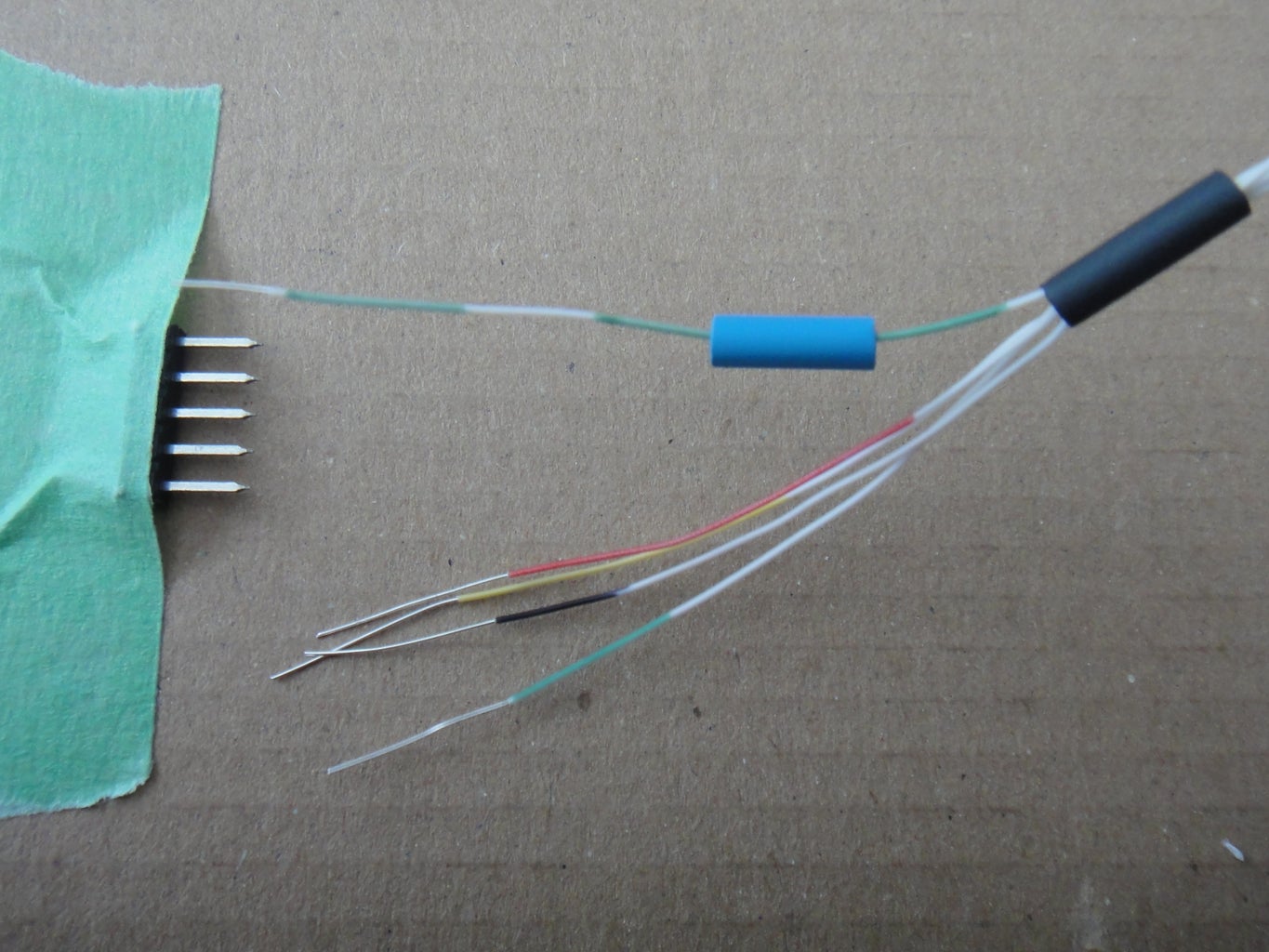


What you see is a five-pin male header, and a bunch of 7mm cuttings of heat shrink tubing.
Carefully slip a black heat-shrink tubing over the entire bundle of wires.
Slip one blue heat-shrink tubing over the wire to be soldered. In the second photo, I am soldering the advance green wire. The order of the pins, from top to bottom will be
- advance green
- green
- yellow
- red
- black (common cathode)
- green
- yellow
- red
- black (common cathode)
- strip off about an inch of insulation from the end of each wire, and then use wire nippers to cut the stripped end to the same length as the long pins on the male header,
- pre-tin the long leads of the male header by touch a soldering iron to them, and then flowing on some solder to coat the pin
- hold the end of the wire to a male header pin, touch the soldering iron the the header, and remelt the solder and force the wire into it
- remove the soldering iron and hold the wire steady while the solder cools
- inspect for a shiny colder joint, not a frosty cold-solder joint, reheat if required to get a shiny solder joint
Keep the heat shrink tubing well away from the soldering iron, as shown. The surrounding heat from a 25-Watt soldering iron is enough to shrink the tubing.
When the assembly is cool, push all the heat shrink tubing over the solder joints and then use a heat-shrink gun (or the heat from a soldering iron) to shrink the tubing over the pins and wire bundle.
Step 19: Cut Slots in the LEGO Road Plate


After deciding where the lamp posts should be on the base, we need to cut slots in the base so that the connectors can fit through.
You can look at the last photo in this step to see where I decided to mount my lamp posts.
The first photo below is of the slot. I used a single-edged razor blade and slowly scored the plastic until I got through. You can see where the knife slipped a few times. Another way to do this, if you have a drill, is drill two holes at either end of the slot, and then cut out between the holes.
The second photo shows a connector going through the slot that was just cut.
The last photos show the light connected to the road plate. Notice how the wires completely disappear.
Step 20: Circuit Schematics


With the traffic lights assembled, we're on to the electronics.
Schematic & Breadboard
The first picture is the schematic for the circuit. If you don't know how to read a schematic, it might be wise to find a website or book that can help you out. Notes on the image will help you.
For those that want to forego the whole LEGO part of the build, I've included a breadboard layout of the T-intersection traffic light.
The third picture is a closeup of an Arduino Nano, so that you can familiarize yourself with the pin layout, which will make the steps that follow easier to understand.
You can learn more about the nano here: http://www.arduino.cc/en/Main/ArduinoBoardNano
For those that would like to build a cross-intersection, I've included a schematic and breadboard layout for that as well. It just barely fits on a single breadboard.
LED Matrix
Look closely at the schematic and you'll see that the LEDs are arranged in a matrix. This is even more evident in the cross-intersection schematic. The Nano has enough Input/Output pins to drive all 10 LEDs directly, but a matrix is can reduce the number of Output pins that are needed. For the T-intersection, seven Output pins operate 10 LEDs; for the cross-intersection, eight pins drive 16 LEDS. (That leaves extra pins to add a pushbutton later on to change modes, as well as possibly add pedestrian crossing lights. These are just ideas, I haven't programmed anything yet.)
Persistence of Vision
With a matrix, only one set of traffic lights can be lit at a time.
Using Persistence of Vision, we can fool the eye into thinking all three traffic lights are being lit at the same time. First, the left traffic light is lit for a small moment of time, then the one at the top of the T and then the right one. Repeat this cycle rapidly enough and it will appear to the eye that all the traffic lights are on at the same time.
All three lights need to be cycled at least 60 times per second to fool the eye. This is called a refresh rate. (In the video on the intro page, 60 times per second wasn't fast enough to fool the video camera: they appear to flicker.)
There are 1000ms (milliseconds) in 1 second: 1000 / 60 is approximately 16ms. All three lamp posts must be lit within 16ms. Calculating 16ms / 3 lamp posts is approximately 5ms. Each lamp post will be lit for 5ms out 16ms, 60 times every second.
The number 5 appears in the code as the DISPLAY_PERIOD constant. Make that number bigger and you'll start to see the lights flicker.
For a cross-intersection, 16ms / 4 lamp posts is 4ms.
Matrix operation
The wires that go to the resistors are the drive lines. When the drive lines are all at ground, zero volts, no LEDs will light. If we make one line logical high, positive voltage, we are driving that lamp post.
The cathode lines are the reverse of the drive lines. Normally these will be logical high, positive voltage. An LED that receives positive voltage on both pins will not light: current can't flow. Take one of the cathode lines to logical low, or zero volts, current can flow from the positive anode through the LED to the zero voltage cathode: it will light up. Through software we can control each LED in turn.
(Current actually flows from negative to positive, but it's simpler to think of it from the positive terminal of the battery, through the LED, to the negative terminal of the battery.)
Step 21: Explaining the Code


I'm only going to explain the simple part of the code. If you can understand that piece, when you open the code file you'll be able to understand the part that actually cycles the LED's of the traffic lights.
Cycle arrays
The first picture defines a four arrays. Together they define the state of the traffic light at any point in time, as well as how long that state exists before the next state will appear. The code cycles through this array and when it reaches the end, it will start again at the beginning of the array, forever.
Outputs and setup
The second picture shows how some constants are defined that map the outputs to the LED anodes and cathodes and then shows how the setup function performs a lamp test. When the micro-controller is first turned on, all the LEDs of each lamp post are lit in turn for five seconds. This is so you can verify that all the LEDs are operating correctly. If you see anything funky at this phase of the program, you've either made a wiring error, a wire has broken or an LED is burnt out.
Lamp test
In the last picture, the functions that make up the lamp test are shown. Follow the code to see that all the lights on the left lamp post are lit for five seconds, followed by the cross lamp post at the top of the T, and finally the right lamp post. Now here's the interesting bit. If you were to reduce that delay from 5 seconds to 5 milliseconds and perform the lamp test in a loop instead of once, it would appear that all the LEDs on all the lamp posts are on! That's how multiplexing LEDs works. With that, you should be able to follow how the rest of the code simply substitutes in the lamp state defined in the cycle arrays, instead of turning on all the lights.
Step 22: Wiring Up the Circuit


My intent was to make the circuit as compact as possible as it was going to be placed into a LEGO structure. Given that, there is no printed circuit board, nor proto-board, something electronic hobbyists use to make a single copy of a circuit.
Instead, I cut a 2-by female header to 15-pins long, one for each set of the pins on the Nano board. I then cut another 2-by female header 5-pins long, and used hot-glue to glue it to the 15-pin female header. Hot-gluing the small header to the big header was tricky and I had to pull it apart and re-glue it several times to get the tops of the headers flush. It was also important to get the pins on the bottom properly lined up, as I soldered the resistors right to the headers.
The second photo shows how the resistors were soldered directly to the pins of the headers. Note the use of heat-shrink tubing again to prevent short-circuits. A circuit built this way is very dense. You want to connect one lead of the resistor to what will be the output pin of the Nano. The other lead of the resistor shorts together all three of the remaining header pins. Repeat that process for wiring each resistor. In the photo, some of the connections have been hidden by resistors sitting on top of resistors underneath. When in doubt, follow the schematic and just make sure you solder the resistor to the correct pin numbers.
The way the resistors are oriented, they will lie underneath the Nano when the header is plugged onto it.
Step 23: Build the Arduino Nano Dumpster


I wanted the Arduino Nano to be hidden inside LEGO. So I built what was supposed to be one of those grey housings that you see near a set of traffic lights: the controller circuitry. Mine ended up looking like a dumpster.
In this Instructable I'm using a 9-volt battery to power the Nano. On our LEGO Train layout, I have a dedicated wall-wart power pack. So my dumpster doesn't have room for the battery. You could build yours to house a battery if you wish.
I'm not showing a parts list for the dumpster, because it's not really part of the Instructable. Build what you want. These photos are intended as inspiration.
Step 24: Connect Traffic Lights to Arduino Nano


This photo shows the female header mounted to the Nano. Notice that I didn't plug the Nano into the header fully in this photo to illustrated how it connects. You'll want to fully seat the Nano into the header.
The first set of lights, the one with the advance green light, plug into the 15-pin female header, in-line with the one that was glued on.
The cross light at the top of the T-intersection plugs into the first row of the glued on header, followed by the light on the right of the T-intersection, which plugs into the last row on the glued on connector.
For a cross-intersection you would have glued on one more 1 x 5 header. The traffic light at the bottom of the intersection would plug into that header.
Make sure you get the common cathode (the black heat-shrink tubing) all facing the correct way.
Step 25: Program Code

It's time to test it all out.
Download and rename
Code files are attached to the article. They will download with a very strange name with a .tmp suffix. You need to rename the file to have a .ino suffix. The file also needs to be placed in a folder with the same name as the file; an artifact of how the Arduino IDE organizes code.
You can also visit the GitHub repo and get the code from there. It has the correct directory structure already set up. https://github.com/Maloffstrano/arduino-traffic-light/
Program the Nano
Load the INO file into the Arduino IDE (Integrated Development Environment) editor. Use the IDE to program the micro-controller with the code. Programming instructions are available on the Arduino site. Choose your platform, Windows, Mac or Linux and follow the instructions.
Getting started: http://www.arduino.cc/en/Guide/HomePage
Arduino Nano programming: http://arduino.cc/en/Guide/ArduinoNano
Try it
After programming the Arduino Nano, connect the battery and watch. The software goes through the lamp test phase followed by run mode. The traffic lights start out all red and then run through each cycle forever.
Cross-intersection
For those that are building a cross-intersection, you'll want to download the file LEGO_LED_Cross_Intersection.ino. Once again, rename it to the correct name should it download with a funky name and a tmp extension.
The cross-intersection code includes two different sequences. The one I thought was the most logical has been uncommented. If you want to enable the second sequence, simply comment out the first and uncomment the second. Both sequences are fully commented and they have vastly different sized cycle arrays that should help you understand the state-machine nature of the code even more.
The cross-intersection code also has a few additional tweaks to make it a bit simpler and has more comments so you can understand the pseudo-event driven programming style that I've used.
If you're stumped by the code, leave a comment and I can always try to explain.

Step 26: Finish Up the Underside


Leaving loose wires on the underside of the plate isn't very nice. They can snag on things when the plate is slid around. I used clear duct tape to hold them down.
After taping I flipped the plate back over to see what looks like a hurricane went through the intersection. LEGO can break. Just fit it back together gently without kinking or pinching any of the wires. You can choose to glue the LEGO together if your wish. I didn't bother.
Step 27: Street-level View and Feedback


Street-level view
These are some pictures of the final working traffic lights, taken from the perspective of the LEGO mini-figs that inhabit this intersection.
A typical 9-volt rechargeable battery will power these lights for about 8 hours.
Feedback
This is my first Instructable. If you've taken the time to either read through this please leave me a comment. If you've actually built one, attach a picture. My son, who helped with my first build would be tickled to see what other have come up with.
Parting thoughts
A T-intersection doesn't have many build opportunities. I added an advance turn light to make it more interesting. That's about all the possibilities: three standard lights or one with an advance green.
A cross-intersection has many possibilities. I've illustrated a schematic where all the lights have advance turns. You can add interest if you want to take up a bit of coding and have fewer advance greens. You could make it so that only one traffic light can be green at a time to simulate a really busy intersection. You could extend the cycle array so that some lights only have an advance green every other cycle. Or you could do that with an additional bit where the bit-constants are defined. There are many more possibilities. I look forward to seeing what you come up with.
Participated in the
Microcontroller Contest


