

Introduction: LINUSBot - Line Follower Robot


The operation of this Robot is quite simple.
Infra-red sensors placed at the front of the chassis will monitor when our Robot is over a black line or when it is over a white background.
In this project we will use the appropriate rounded chassis to the Robot.
In case the robot being on the black line, it will always go ahead, and in the case of out of line and fall into a white area, it will determine whether to correct to the left or right, and thus remain on the black line.
The sensors that will be used is the array infrared sensor Pololu (also called reflectance sensors) QTRx8RC, that consists of eight sensors (only five are used) QRE1113GR.
This array has a digital output and can easily be managed using the appropriate library of Pololu, for determine the position of the line relative to the sensors.
This array of sensors can be broken in a array with 6 sensors and another with 2 sensors.
For more information about the sensors array , visit:
http://www.pololu.com/catalog/product/961
In this first project, we will use a raw control for our robot, ie we are concerned to keep the robot following the line ...
The Robot will run in a track and we will note that the motions of the robot will be somewhat "robotic", ie: not very smooth, but jerky.
See http://arduinobymyself.blogspot.com.br for more projects.
Step 1: The Track


The track will be made of a piece of white cardstock and black electrical tape.
The bend ought to a minimum diameter 6" or greater.
Below we have two examples of track
Step 2: Hardware and Components


1 X Arduino UNO, Mega, Duemilanove or Teensy + + 2.0
1 x prototype shield (optional) (highly recommended)
1 x dual H-BRIDGE
2 x Gear Box with 30:1 of ratio transmission and associated DC motor
2 x wheels 3"
2 x 9V Batteries 400 mA / h
2 x 9V battery clip
1 x Ball caster (third wheel)
wires and cables for connections
screws, nuts, washers, spacers for mounting
2 x acrylic parts for cutting the chassis
tools in general
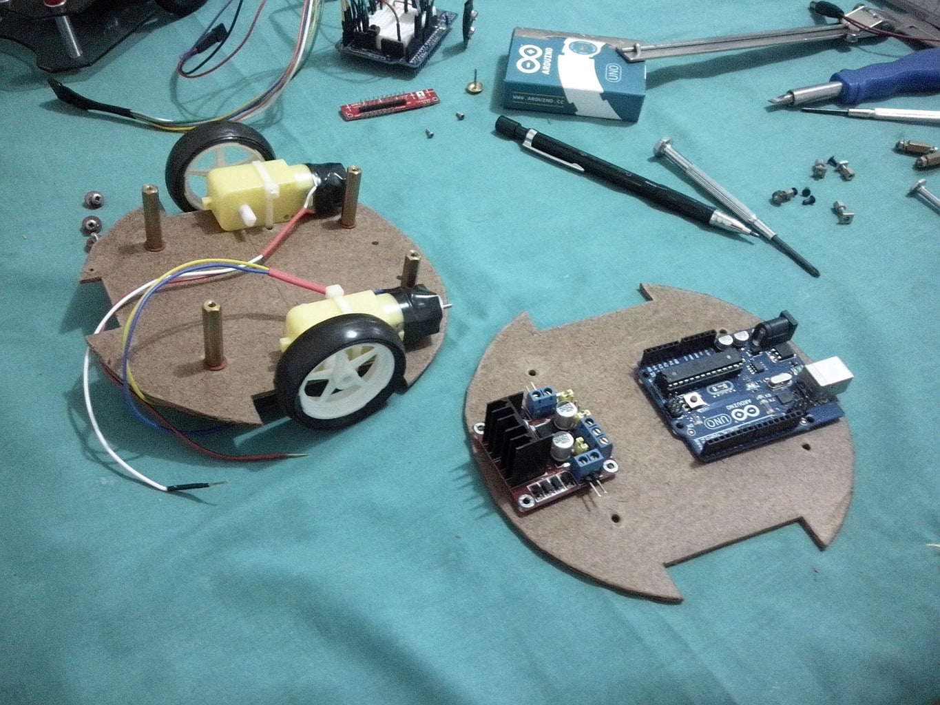
Step 3: Chassis Project


The chassis was constructed with a 3 mm piece of acrylic in a rounded format with slots for the wheels.
See the screenshots below (sorry but is in Portuguese) but can have a general idea.
Step 4: Schematic Diagram

Lets go to the pinouts:
1 - The motors are connected to the output pins of the H-Bridge (care about to the polarity);
2 - The 9V battery is connected to VCC (+) and GND (-) of the H-Bridge;
3 - Pins in1, in2, in3 and in4 of H-bridge are connected to the arduino pins: 10, 11, 5 and 6 respectively;
4 - Pins 1, 2, 3, 4 and 5 of the QTR sensor, are connect to the pins A0, A1, A2, A3 and A4 (notice that the sensor 1 should be the most left);
5 - The LCD is connect as showed in the diagram: pins R / W - 13, Enable - 12, data - 9, 8, 7 and 4 (it dependent of the type of yours display);
6 - The button is connected to pin 2 of the Arduino;
7 - The Buzzer is connected to the Arduino pin 3;
8 - The Battery sensor is connected to pin A5
10K/5K consists of two resistors connected to GND / VCC and the center tap is connected to the arduino. as below
| GND | --- / \ / \ / \ / ------ / \ / \ / \ / ----- | VCC |
10K | 5K
|
A5
Step 5: The Software
You can download the complete software from the link below:
http://www.4shared.com/file/8yKb70LD/LINUSBot_9_3p...
This program follows the Pololu methodology.
Get all files needed to build the project at GitHub: https://github.com/Arduinobymyself/LINUSBot.git
Step 6: The Video
1st Prototype
screencast: http://www.screencast.com/t/mVXhRPWH
youtube: http://www.youtube.com/watch?v=YEzRKP34UGs&feature=youtu.be
2nd Prototype
screencast: http://www.screencast.com/t/6LN3XlDg3cJ
youtube: http://youtu.be/Z046AKObE34
Others Projects:
https://www.instructables.com/id/Basic-Principles/
https://www.instructables.com/id/PINGBot-Explorer-Robot/
https://www.instructables.com/id/Dual-H-Bridge-L298-Breakout-Board-Homemade/
https://www.instructables.com/id/3x3x3-LED-Cube-1/
https://www.instructables.com/id/LINUSBot-Line-Follower-Robot-with-PID-control/
Step 7: Photos


Two prototypes were made the first is a wooden prototype and the second is an acrylic prototype.
See the photos below for more details.

Participated in the
UP! Contest


