

Introduction: Botletics LTE CAT-M/NB-IoT + GPS Shield for Arduino


Overview
The Botletics SIM7000 LTE CAT-M/NB-IoT shield uses the new LTE CAT-M and NB-IoT technology and also has integrated GNSS (GPS, GLONASS and BeiDou/Compass, Galileo, QZSS standards) for location tracking. There are multiple SIM7000-series modules that cater to different regions around the world, and luckily SIMCOM has made it really easy to identify: SIM7000A (American), SIM7000E (European), SIM7000C (Chinese), and SIM7000G (Global). Currently NB-IoT is supported in many countries around the world but unfortunately not in the US, although it's scheduled to be commercially available in the near future (2019) and regardless, we can still use the LTE CAT-M functionalities!
To use the shield, simply plug the shield into an Arduino, insert a compatible SIM card, attach the LTE/GPS antenna, and you're good to go!
Introduction
With the emergence of low-power IoT devices with cellular connectivity and the phase-out of 2G (with only T-mobile supporting 2G/GSM until 2020), everything is moving toward LTE and this has left many people scrambling to find better solutions. However, this has also left many hobbyists facepalming with legacy 2G technology like the SIM800-series modules from SIMCOM. Although these 2G and 3G modules are a great starting point, it's time to move forward and SIMCOM recently announced their new SIM7000A LTE CAT-M module at a developer's conference. How exciting! :)
The amazing part of all of this is that SIMCOM made it extremely easy to migrate from their 2G and 3G modules to this new module! The SIM7000-series use many of the same AT commands which minimizes the software development by miles! Also, Adafruit already has a wonderful FONA library on Github that can be used to introduce this new SIM7000 into the party!
What is LTE CAT-M?
LTE CAT-M1 is considered the second-generation LTE technology and is lower-power and more suitable for IoT devices. NarrowBand IoT (NB-IoT) or "CAT-M2" technology is a Low-Power Wide Area Network (LPWAN) technology specifically designed for low-power IoT devices. It is a relatively new technology that is, unfortunately, not yet available in the US, although companies are working on testing and building the infrastructure. For IoT devices using radio technology (RF) there are several things to keep in mind: Power consumptionBandwidthRangePacket size (send lots of dataCostEach of these have tradeoffs (and I won't really explain them all); for example, large bandwidth allows devices to send lots of data (like your phone, which can stream YouTube!) but this also means it's very power-hungry. Increasing the range (the "area" of the network) also increase power consumption. In the case of NB-IoT, cutting down the bandwidth means that you won't be able to send much data, but for IoT devices shooting morsels of data to the cloud this is perfect! Hence, "narrow"-band technology, ideal for low-power devices with little amounts of data but still with long range (wide area)!
The Botletics SIM7000 Shield for Arduino
The shield that I've designed uses the SIM7000-series to enable users to have extremely low-power LTE CAT-M technology and GPS at the tip of their fingers! The shield also sports an MCP9808 I2C temperature sensor, great for at least measuring something and sending it via a cellular connection.
- The shield is open source! Yay!
- All documentation (EAGLE PCB files, Arduino code, and detailed wiki) can be found here on Github.
- To see which SIM7000 version is most suitable for you, please see this wiki page.
- The Botletics SIM7000 shield kit can be purchased here on Amazon.com
Step 1: Gather Parts


Below is a list of all the parts you will need:
- Arduino or Arduino-compatible board - The Arduino Uno is the most common choice for this! If you want to use the LTE shield as really a "shield" you should use an Arduino board with the Arduino form factor. Stating the obvious, you will also need a programming cable to upload Arduino sketches to the board! If you are not using an Arduino-form-factor board that's fine too! There's info on what connections to make in this wiki page and different microcontrollers have been tested, including ESP8266, ESP32, ATmega32u4, ATmega2560, and ATSAMD21.
- Botletics SIM7000 Shield Kit - The shield comes with a dual LTE/GPS uFL antenna and stacking female headers! The board comes in three different versions (SIM7000A/C/E/G) and depending on which country you live in you will need to select the right version. I've created this page on the Github wiki that shows you how to find out what version is best for you!
- LTE CAT-M or NB-IoT SIM Card - Although the kit no longer includes a free SIM card, you can pick up a Hologram SIM card which gives you 1MB per month for free and works practically anywhere in the world because Hologram has partnered up with over 500 carriers! They also have pay-as-you-go and monthly plans and have a great community forum for technical support on SIM card activation, Hologram APIs, and more! It works great with this shield nation-wide in the USA for AT&T and Verizon's LTE CAT-M1 networks but note that in other countries you may have to get your own SIM card from a local provider since Hologram partners up with carriers and CAT-M and NB-IoT is relatively new.
- 3.7V LiPo Battery (1000mAH+): While searching for networks or transmitting data the shield can draw significant amounts of current and you can't rely on direct power from the Arduino 5V rail. Plug in a 3.7V LiPo battery into the JST connector on the board and make sure the battery is wired with the positive wire on the left (like those found at Sparkfun or Adafruit). Also, it's important to make sure that the battery must have at least 500mAH capacity (bare minimum) to be able to supply enough current and prevent the module from rebooting during current spikes. 1000mAH or greater is recommended for stability. The reason for this bare minimum capacity is because the LiPo battery charging circuitry is set to 500mA so you should make sure that the battery is at least 500mAH capacity to prevent damage to the battery.
Step 2: Assemble the Shield


In order to use the shield you will need to solder headers onto it unless you don't plan on using this board as a "shield" and more of a standalone module instead, which is also perfectly OK! An example of doing this is using an Arduino Micro as the controller and wiring it up to the shield separately.
The most common choice for using the board as an Arduino shield are stacking female headers, which are included with the shield. After soldering the headers, go ahead and place the shield on top of the Arduino board (unless you're using it as a standalone board) and you're ready for the next step!
Note: For tips on how to solder the pins you can visit this page of the Github wiki.
Step 3: Shield Pinouts


The shield simply uses the Arduino's pinout but connects certain pins for specific purposes. These pins can be summarized below:
Power Pins
- GND - Common ground for all logic and power
- 3.3V - 3.3V from the Arduino's regulator. Use this just as you would on the Arduino!
- 5V / LOGIC - This 5V rail from the Arduino charges the LiPo battery which powers the SIM7000 and also sets the logic voltage for the I2C and level shifting. If you are using a 3.3V microcontroller, connect 3.3V to the shield's "5V" pin (please see the section below).
- VBAT - This grants access to the LiPo battery voltage and is normally not connected to anything on the Arduino so you are free to use it as you wish! It's also the same as the input voltage of the SIM7000 module. If you're thinking about measuring and monitoring this voltage, check out the "b" command in the demo tutorial which measures the voltage and displays the battery percentage! Remember, the LiPo battery is required!
- VIN - This pin is simply connected to the VIN pin on the Arduino. You can power the Arduino as you normally would with 7-12V on this pin.
Other Pins
- D6 - Connected to the SIM7000's PWRKEY pin
- D7 - SIM7000's Reset pin (only use this in case of emergency reset!)
- D8 - UART Data Terminal Ready (DTR) pin. This can be used to wake the module from sleep when using the "AT+CSCLK" command
- D9 - Ring Indicator (RI) pin
- D10 - UART Transmit (TX) pin of the SIM7000 (this means you should connect the Arduino's TX to this!)
- D11 - UART Receive (RX) pin of the SIM7000 (connect to Arduino's TX pin)
- D12 - Good 'ole D12 on the Arduino, BUT you can connect it to the ALERT interrupt pin of the temperature sensor by soldering a jumper
- SDA/SCL - The temperature sensor is connected to the shield via I2C
If you are using the board as a standalone module and not as a "shield", or if you're using 3.3V logic instead of 5V you will need to make the necessary connections as detailed in the section "External Host Board Wiring" of this Github wiki page.
However, if all you need is to test AT commands, then you only need to connect the LiPo battery and the micro USB cable, then follow these procedures to test AT commands via USB. Note that you can also test AT commands via the Arduino IDE, but that would require connecting pins D10/D11 for UART.
For detailed information about the shield pinouts and what each pin does, visit this Github wiki page.
Step 4: Powering the Shield

To power the shield, simply plug in the Arduino and plug in a 3.7V LiPo battery (1000mAH or greater capacity) like the ones sold at Adafruit or Sparkfun. Without the battery you will likely see the module boot up then crash shortly thereafter. You can still power the Arduino as you normally would via the USB cable or externally by a 7-12V power source on the VIN pin and the 5V rail on the Arduino will charge the LiPo battery. Note that if you are using a standard Arduino board you can safely power it via an external power source while also keeping the programming cable plugged in because it has voltage-selection circuitry.
LED Indication
At first you might be wondering if the board is even alive because there maybe not be any LED's turning on. This is because the "PWR" LED is a power indicator for the SIM7000 module itself, and although you are supplying power you haven't turned the module on yet! This is done by pulsing the PWRKEY low for at least 72ms, which I'll explain later. Also, if you have a battery connected and it's not fully-charged the green "DONE" LED won't turn on, but if you don't have a battery connected this LED should turn on (and might flash occasionally when it's tricked into thinking the nonexistent battery isn't fully-charged due to slight voltage drops).
Now that you know how to power everything let's move on to the cellular stuff!
Step 5: SIM Card & Antenna


Choosing a SIM Card
Again, your SIM card needs to be able to support LTE CAT-M (not just traditional LTE like what's probably in your phone) or NB-IoT, and it has to be a "micro" SIM size. The best option I've found for this shield is the Hologram Developer SIM card which provides 1MB/month for free and access to Hologram's APIs and resources for the first SIM card! Simply log on to your Hologram.io dashboard and enter the SIM's CCID number to activate it, then set the APN settings in the code (already set by default). It is hassle-free and works anywhere in the world because Hologram supports over 200 carriers globally!
It should be noted that the SIM7000C/E/G versions also support 2G fallback, so if you really want to test and don't have a LTE CAT-M or NB-IoT SIM card, you can still test the module on 2G.
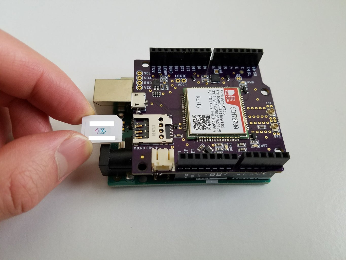
Inserting the SIM Card
First of all you should make have to break the micro SIM out of the normally-sized SIM card holder. On the LTE shield locate the SIM card holder on the left side of the board near the battery connector. The SIM card is inserted into this holder with the SIM's metal contacts facing down and the little notch on one edge facing the SIM card holder.
Antenna Goodness
The shield kit comes with a really convenient dual LTE/GPS antenna! It's also flexible (although you shouldn't try to twist and bend it a lot because you might break the antenna wires off the antenna if you're not careful) and has a peel-away adhesive on the bottom. Connecting the wires is super simple: just take the wires and snap them onto the matching uFL connectors on the right edge of the shield. NOTE: Make sure you match up the LTE wire on the antenna to the LTE connector on the shield, and the same with the GPS wire because they're criss-crossed!
Step 6: Arduino IDE Setup

This SIM7000 shield is based on the Adafruit FONA boards and uses the same library but improved with added modem support. You can read full instructions on how to install my revised FONA library here on my Github page.
You can also see how to test out the MCP9808 temperature sensor by following these instructions, but here I'll mainly be focusing on the cellular stuff!
Step 7: Arduino Example


Baud Rate Setup
By default the SIM7000 runs at 115200 baud but this is too fast for software serial to reliably operate and characters might randomly appear as square boxes or other odd symbols (for example, an "A" could show as "@"). This is why if you look carefully, the Arduino configures the module to a slower baud rate of 9600 every time it's initialized. Fortunately the switching is taken care of automatically by the code, so you don't need to do anything special to set it up!
LTE Shield Demo
Next, follow these instructions to open the "LTE_Demo" sketch (or whichever variation of that sketch, depending on which microcontroller you are using). If you scroll down to the end of the "setup()" function you will see a line "fona.setGPRSNetworkSettings(F("hologram"));" which sets the APN for the Hologram SIM card. This is absolutely needed, and if you are using a different SIM card you should first consult the card's documentation on what the APN is. Note that you only need to change this line if you are not using a Hologram SIM card.
When the code runs the Arduino will attempt to communicate with the SIM7000 via UART (TX/RX) using SoftwareSerial. In order to do this, of course, the SIM7000 has to be powered on, so while it's trying to establish a connection, check for the "PWR" LED to make sure it turns on! (Note: it should turn on about 4s or so after the code runs). After the Arduino successfully establishes communication with the module you should see a large menu with a bunch of actions the module can perform! However, note that some of these are for SIMCom's other 2G or 3G modules so not all of the commands are applicable to the SIM7000 but lots of them are! Simply type the letter corresponding to an action you want to perform and click "Send" at the top right of the serial monitor or simply press the Enter key. Watch in amazement as the shield spits back a reply!
Demo Commands
Below are some commands you should run to make sure your module is set up before proceeding:
- Type "n" and press enter to check the network registration. You should see "Registered (home)". If not, check if your antenna is attached and you may also have to run the command "G" (explained below) first!
- Check the network signal strength by entering "i". You should get an RSSI value; the higher this value the better! Mine was 31, which indicates the best signal strength bracket!
- Enter the command "1" to check some really cool network info. You can get the current connection mode, carrier name, band, etc.
- If you have a battery connected, try the "b" command to read the battery voltage and percentage. If you're not using a battery this will command will always read around 4200mV and therefore say it's 100% charged.
- Now enter "G" to enable cellular data. This sets the APN and is crucial for getting your device connected to the web! If you see "ERROR" try turning data off by using "g" then try again.
- To test if you can actually do something with your module, enter "w". It will prompt you to enter the URL of the webpage you want to read, and copy/paste the example URL "http://dweet.io/get/latest/dweet/for/sim7000test123" and press enter. Shortly thereafter it should give you a message like "{"this":"failed","with":404,"because":"we couldn't find this"}" (assuming no one posted data for "sim7000test123")
- Now let's test sending dummy data to dweet.io, a free cloud API by entering "2" in the serial monitor. You should see it run through some AT commands.
- To test if the data really got through, try "w" again and this time enter "http://dweet.io/get/latest/dweet/for/{deviceID}" without the brackets, where the device ID is the IMEI number of your device which should be printed at the very top of the serial monitor from the module initialization. You should see "succeeded" and a JSON response containing the data that you had just sent! (Note that the 87% battery is just a dummy number that is set in the code and may not be your actual battery level)
- Now it's time to test the GPS! Enable power to the GPS using "O"
- Enter "L" to query the location data. Note that you might have to wait around 7-10s before it will get a fix on the location. You can keep entering "L" until it shows you some data!
- Once it gives you data, copy and paste it into Microsoft Word or a text editor so that it's easier to read. You will see that the third number (the numbers are separated by commas) is the date and time, and the next three numbers are the latitude, longitude, and elevation (in meters) of your location! To check if it was accurate, go to this online tool and search your current location. It should give you the lat/long and altitude and compare these values with the one your GPS gave!
- If you don't need GPS you can turn it off using "o"
- Have fun with the other commands and check out the example "IoT_Example" sketch for a cool example on how to send data to a free cloud API via LTE!
Send & Receive Texts!
To see how to send texts from the shield directly to any phone and send texts to the shield via Hologram's Dashboard or API, please read this Github wiki page.
IoT Example: GPS Tracking!
Once you verify everything is working as expected, open the "IoT_Example" sketch. This example code sends GPS location and bearing data, temperature, and battery level to the cloud! Upload the code and watch in amazement as the shield does its magic! To check if the data was really sent to the cloud, go to "http://dweet.io/get/latest/dweet/for/{IMEI}" in any browser (fill in the IMEI number found at the top of the serial monitor after module initialization, or printed on your SIMCOM module) and you should see the data that your device sent!
With this example you can also uncomment the line with "#define samplingRate 30" to send data repeatedly instead of only running once. This makes your device essentially a GPS tracking device!
For more details, please visit the tutorials I made for real-time GPS tracking:
Troubleshooting
For common questions and troubleshooting issues please visit the FAQ on Github.
Step 8: Testing With AT Commands

Testing from Arduino IDE
If you want to send AT commands to the module via the serial monitor, use the "S" command from the menu to enter serial tube mode. This will make it so that everything you type in the serial monitor will be sent to the module. That being said, make sure to enable "Both NL & CR" at the bottom of the serial monitor, otherwise you won't see any response to your commands because the module won't know you're done typing!
To exit this mode, simply press the reset button on your Arduino. Note that if you are using ATmega32u4 or ATSAMD21-based boards, you will have to restart the serial monitor as well.
For more info about sending AT commands from the Arduino IDE, please see this wiki page.
Testing Directly Via USB
Perhaps an easier method (for Windows users) is to install the Windows drivers detailed in this tutorial and test AT commands by using the shield's micro USB port instead!
If you still want to experiment with the AT commands but want to run them in a sequence and don't want to mess with altering the FONA library you can do that with a simple little library I wrote called the "AT Command Library" which you can find here on Github. All you need to do is download the ZIP from the repository and extract it into your Arduino libraries folder and an example sketch (called "AT_Command_Test.ino") for the SIM7000 can be found here in the LTE shield Github repo. This library allows you to send AT commands via Software Serial with timeouts, checks for a specific reply from the module, neither, or both!
Step 9: Current Consumption
For IoT devices you want to see these numbers to go way down, so let's take a look at some of the tech specs! For a detailed report of current consumption measurements, please see this Github page.
Here's a quick summary:
- SIM7000 module powered off: entire shield draws < 8uA on 3.7V LiPo battery
- Sleep mode draws about 1.5mA (including the green PWR LED, so probably ~1mA without it) and stays connected to the network
- The e-DRX settings can configure the cycle time of the network negotiation and save energy but also will delay things like incoming text messages depending on what the cycle time is set to
- Connected to LTE CAT-M1 network, idle: ~12mA
- GPS adds ~32mA
- Connecting USB adds ~20mA
- Data transmission over LTE CAT-M1 is ~96mA for ~12s
- Sending SMS draws ~96mA for ~10s
- Receiving SMS draws ~89mA for ~10s
- PSM sounds like a wonderful feature but has yet to work
And here's a little more explanation:
- Power Down Mode: You can use the "fona.powerDown()" function to completely power off the SIM7000. In this state the module draws only about 7.5uA, and shortly after you turn off the module the "PWR" LED should also turn off.
- Power Saving Mode (PSM): This mode is like the power down mode but the modem remains registered to the network while drawing only 9uA while still keeping the module powered. In this mode only the RTC's power will be active. For those ESP8266 fans out there, it's basically "ESP.deepSleep()" and the RTC timer can wake up the module but you can do some pretty cool stuff like wake the modem up by sending it an SMS. However, unfortunately I could not get this feature to work. Definitely let me know if you do!
- Flight Mode: In this mode power is still supplied to the module but RF is completely disabled but the SIM card is still active as well as UART and USB interface. You can enter this mode using "AT+CFUN=4" but I did not see this take effect either.
- Minimum Functionality Mode: This mode is the same as Flight Mode except the SIM card interface is inaccessible. You can enter this mode using "AT+CFUN=0" but you can also enter this mode using "AT+CSCLK=1" after which the SIM7000 will pull up the DTR pin when the module is in idle mode. In this sleep mode pulling DTR low will wake up the module. This can be handy because waking it up can be a lot faster than powering it up from scratch!
- Discontinuous Reception/Transmission (DRX/DTX) Mode: You can configure the "sampling rate" of the module so to speak, so that the module only checks for text messages or sends data at a faster or slower rate, all while remaining connected to the network. This significantly reduces the current consumption!
- Disable "PWR" LED: To save a few more pennies you can disable the module's power LED by cutting the normally-closed solder jumper next to it. If later you change your mind and want it back, just solder the jumper!
- "NETLIGHT" LED On/Off: You can also use "AT+CNETLIGHT=0" to turn off the blue network status LED completely if you don't need it!
- GNSS On/Off: You can save 30mA by turning off GPS using the command "fona.enableGPS()" with true or false as the input parameter. If you're not using it I'd suggest you to turn it off! Also, I found that it only takes about 20s to get a fix on location from a cold start and only about 2s when the device has already been on (like if you turn GPS off then back on and query again), which is pretty fast! You can also experiment with warm/hot start and assisted GPS.
Attachments

Step 10: Conclusions
Overall, the SIM7000 is super fast and uses cutting-edge technology with integrated GPS and comes loaded with cool features! Unfortunately for those of us in the United States, NB-IoT is not fully deployed here so we will have to wait a bit until it comes out, but with this LTE shield we can still use LTE CAT-M1 on AT&T and Verizon's networks. This shield is great for experimenting with low-power cellular devices like GPS trackers, remote dataloggers, and much more! By including other shields and modules for things like SD card storage, solar panels, sensors, and other wireless connectivity, the possibilities are almost endless!
- If you liked this project, please give it a heart and vote for it!
- If you have any comments, suggestions, or questions, feel free to post it below!
- To order your own shield, please visit my website for info or order it on Amazon.com
- As always, please share this project!
With that said, happy DIY'ing and make sure to share your projects and improvements with everyone!
~ Tim

Participated in the
Wireless Contest


