

Introduction: Large 7 Segment Clock


I like to make stuff. But, I will be honest with you. I was not gifted with endless ideas. Lack of creativity? No, I will solve any problem. Lack of time/money/energy? Always. In addition, anything I make has to serve some useful purpose. Creating a large clock seemed like a good thing to someone whose vision prescription strength is -6.5. A clock is practical, it allows me to build something presentable, and was my first leap into coding. I won't even begin to talk about the billions of problems I ran into along the way. Let me just tell you I am impatient. PLANNING GOES A LONG WAY.
**This is not a bomb**
#IStandWithAhmed
Step 1: Materials & Tools
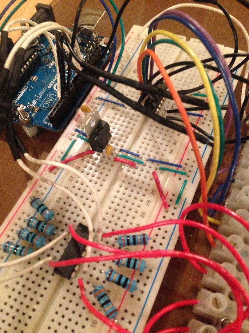
Essential Materials
- Arduino Uno R3
- Breadboard >30 Nodes
- Wire (Solid, 22 AWG)
- Terminal Block (at least 12 poles)
- x4 6.5" 7-Segment Displays
- TI SN74LS47 BCD-to-7-segment Decoder
- Quad array NPN BJT Transistor (MPQ2222)
- x4 P-Channel MOSFETs (NDP6020P)
- x8 10k Resistors 1/4W
- 5VDC Linear Regulator (12VDC input, 5VDC output)
Essential Tools
- Drill
- Drill Bits (1/4", ...)
- Wire Strippers / Cutters
- Screw Driver
Optional Materials (To create a nice package)
- x12 10-24 x 3/4" Couplers
- x4 10-24 x 2" Threaded rod
- x24 Bonded washers
- x8 10-24 x1/2" stainless steel button cap screw
- Nylon spacers, machine screws, and nuts to mount the Arduino, terminal strip, and 7-segment-displays.
- x3 Transparent Gray Custom Polycarbonate Sheets (x2 9"x20"; x1 9"x20")
- Heat Shrink Tubing
- DC Barrel Jack
Optional Tools
Step 2: The Schematic


The 7-segment displays from Sparkfun are common anode and therefore sourcing current to the display was a big challenge (Common cathode would have been SO much easier). Two schematics are included so you can see where I went wrong with the first design. The better design included MOSFETs.
Decoder
Pins 3-5 on the decoder are all tied to 5VDC. Pin 16 = 5VDC. Pin 8 = GND. Pins 9-15 ground the various segments of the displays when activated. Pins 1,2,6,7 are the control pins. See the product specification linked in the material step for all the info on the decoder.
Step 3: The Code
I am not a programmer. So I wrote the most simple code to run my clock. This code is intended to be a learning tool for people like me who struggle with coding. In the future I will use at RTC... maybe. The code is annotated as much as possible to help you out.
The code will show you the simplicity and value in manipulating the I/O ports on the Arduino directly but setting register values. Not as intuitive as the functions, but enables to code to execute much faster (as needed for the clock).
The clock display has a Multiplexed Display. If you don't understand the Wiki Article, as the annotations will explain, adjusting the Pause "Variable" will give you a good idea of what is happening.
Attachments

Step 4: The Clock


As you can see, the three polycarbonate sheets sandwich the clock. The smaller sheet is in the middle with a 1" gap from the bottom to allow the wires to pass around to the breadboard. Screws hold everything but the breadboard into place (adhesive backing). I strongly recommend getting an abrasive resistant polycarbonate sheet. It will end up looking much nicer.
Suggestions for Improvement
- Add a momentary button to allow the time to be incremented without having to reprogram the clock. The clock time can be calibrated by pushing the rest button. This will take you to the time that was defaulted in the code.
- Use a Real Time Clock (RTC) circuit. Currently the clock will work until the millis() register overflows. ~50days. Once that happens the time will need to be recalibrate. An RTC will resolve this problem and any problems with accuracy. Clock still needs a bit of calibration. The clock time will deviate from any official clock because of the inaccuracies with the Arduino CPU clock.
- Power the Arduino with a Li-ion battery pack to preserve the time if the clock gets unplugged from its 12VDC power supply.


