

Introduction: Laser Crown


I love some of the new wearable stuff that's showing up on Adafruit, Hackaday and Make Magazine. When I saw Adafruit's new 60 LED Neopixel Ring, I knew exactly what I wanted to build for my daughters... I had made a previous attempt at head wear for the Father-Daughter dance last month but out of failure comes inspiration.
Presenting the Laser Crown for the princesses in your life!
The Laser Crown is stunningly bright, lightweight and comfortable. It has no visible wires, USB chargeable, completely programmable, lasts 1-6 hours, has a replaceable battery, expandable, compatible with most arduino type microcontrollers and can be built in an afternoon. And you get to use a laser cutter...
Oh, and the princess gets to look stunning!
Did I mention lasers?
Shall we begin?
**Update*** After some new modifications, I've managed to fix the breakage problem, create the crown pattern on a single 11 X14" sheet of 3mm acrylic and make it a whole lot easier to create. I have heard comments that the vanes are too sharp but a finger nail clips or wire clippers would fix that if you were worried about pointy things. Flame polishing could help too.
Step 1: Skills That May Be Helpful

- Computer Skills (Arduino, OpenSCAD)
- Laser Cutting
- Soldering
- Embedded Electronics
- Patience
This is an advanced project but with persistance doable. All these skills are acquirable through online tutorials, collaboration, maker spaces, etc.
You might not have all of these but it might be fun to meet people who do know how to do different parts of the project. You might learn something while you're at it for a future project. but without duplicating the work others have done much better than I could on the rest of the internets.
Step 2: Overview

These are the steps you'll take.
- Gather Tools and Equipment.
- Acquire or purchase components.
- Install Software.
- Cut the Acrylic.
- Cut the felt.
- Solder the components.
- Flash the microcontroller.
- Connect and test the ring.
- Glue on felt pocket
- Apply vanes
- Present to Princess
Step 3: Equipment Needed

- Laser Cutter (40W or greater)
- Soldering Iron
- Wire stripper
- Access to a computer with Arduino programming software
- Hot glue gun with glue
- Calipers (Highly recommended to get the tolerances you need)
Most of these items can be found at a local hackerspace or makerspace but you read Instructables and I suspect you'll be resourceful.
Step 4: Build of Materials

- 4 - 1/4 segments of NeoPixel 1/4 60 Ring - WS2812 5050 RGB LED w/ Integrated Drivers
- 1 - Adafruit Trinket - Mini Microcontroller - 3.3V Logic
- 1 - JST-PH 2 pin SMT Connector
- 1 - Lithium Ion Polymer Battery 3.7V 1200MAH (Can use a bigger one if you wish)
- 1 - Adafruit Micro Lipo - USB LiIon/LiPoly charger (or similar)
- 14" x 11" (360mm x 280mm) 1/8" (3mm) Acrylic Sheet (6 Crowns on a 24 x 48" Sheet)
- Black Felt
- Remote Control Servo Extension Cord Cable Wire. I used a 3 pin/wire male female extension wire typically found with RC equipment.
- Hot glue stick
- Possibly Acrylic Glue
- USB cable A/Minib
- Do not forget the hair clips!
I am not endorsing any particular source for the components but I've included the links to sources where I got most of my parts. I have been very satisfied with my interactions with these companies. The current cost of the electronics is close to $65 USD. Acrylic sheet is about $27 USD but you could cut 6 crowns from a 2x4 ft sheet. Having someone cut the acrylic for you professionally is around $40 USD. So total build is around $100 USD. You'll still need black felt. If you have access to a laser cutter the costs go down. Most definitely but most of this project revolves around the lovely 60 LED Neopixel Ring from Adafruit that is bright and stunning under the acrylic. Make sure you DO NOT purchase polycarbonate or Lexan. It's tempting because it's much less brittle but using lasers on polycarbonate releases cyanide gas potentially making you sick and damaging your equipment.
Step 5: Software to Install

The software you need to install is dependent on your needs and how you choose to proceed. This is all free open source software and available to Mac and Windows machines and probably Linux as well.
Microcontroller software
I highly recommend following the Adafruit tutorial on the Trinket. Follow the instructions closely on installing the microcontroller software to program the board. It's not as straightforward as programming a regular Arduino board but still quite simple. You'll need their Arduino software and then specific drivers for the Trinket. Again, they've done a spectacular job of explaining and demonstration. If you're using you're own Arduino or similar, you will obviously need to proceed as you see fit. I've including the demo code in this Instructable that is particular to the Trinket but it's easily adapted to an Arduino device using the Adafruit Neopixel Libraries.
Laser cutting software
Every laser is different but most laser cutting software/drivers can accept DXF files. DXF files are vector files that simply tell the laser what lines to cut. If you're cutting this yourself, you'll need to familiarize yourself with DXF importing and the other parameters for your laser. The DXF file I've included assumes a beam width of .3mm (100mm lens) so if you use a smaller lens with a tighter kerf, you might want to cut the rings and then cut just a few vanes. You may have to enlarge or shrink the vanes a bit to accommodate the specs of the laser. (This may just be my obsession and it might not matter which lens you use)
OpenSCAD
I've programmed the whole thing in OpenSCAD message me if you're interested in the file. It's fairly complicated because I really wanted it to snap together. It takes about 3 hours to render because OpenSCAD is terribly slow for some things.
Step 6: Laser Cutting

Laser cutting is one of the coolest processes to watch and learn how to do. It opens up new worlds for you. If this is your first laser cutting project, good for you but prepare to do some learning. Before we continue I am going to presume two things.
- You have 3mm thick acrylic.
- Your laser is well aligned in the X, Y and Z axis.
The tolerances are very tight for this project. I wanted to be able to snap things together and glue them later if needed. If the tolerances weren't tight then the spires do not stand up straight unless you glue them. After you glue them, then you're unable to access the ring for troubleshooting.
I am using a laser cutting lens of 100mm in focal length. A 55mm might work just fine. The benefits of the cutting lens is the beam width is more constant through depth of the material but since I've moved to a uniform 1/8" (3mm) sheet of acrylic that shouldn't pose much of an issue.
Step 7: Cutting the Acrylic Part 1


The DXF file now has both the vanes and rings. Initially I designed it from two thicknesses of acrylic, but good design and manufacturing encourages simplicity. You'll want to cut the whole sheet all at once.
Place the acrylic in your machine, load the DXF file, make sure everything is aligned and press start. (Always the most exciting part!)
Wait. I was just getting ahead of myself.
You'll need to determine the amount of power to use, the feed rate, and the number of passes. The laser I used was a 100W CO2 laser so I could cut at 30mm/sec at 95% power with one pass. All of these variables are dependent on your machine, the usage of your laser tube and sometimes the weather outside (humidity and temperature).
What I would recommend is figure out how to cut a small circle of 1/2" (12mm) diameter first. See how little power and how slow you need to go before you can cut through that acrylic. You want really smooth edges so that means a very slow pass and if your machine can change it's frequency, a lower frequency. You may need to run multiple passes with a lower powered laser. Asking for advice from someone locally with experience also never hurts.
Now to the next step...
Attachments

Step 8: Cutting the Acrylic Part 2


The vanes are where most of the innovation, design and effort went. The height of the vanes varies from the back to the front from a Sine wave function. They are angled so that the internal inner surface reflects the light coming from the NeoPixel. I had some other designs which seemed clever but they proved to not be to my liking since most of the light did not radiate outwards. The bottom of the vanes have angles and slots cut out so that they snap into the rings. One trick I learned from the Ponoko blog is that sharp angles cut in acrylic really need very small radii to prevent the acrylic from cracking. I experienced about 20-30% failure without the feature. The current DXF file includes that feature and I have not had one break after I included the technique.
The rings are not as fragile made from 1/8" (3mm). I had designed them much thicker and they were nice and chunky but having a pair of rings makes construction a little easier. The top ring will be covered by the Neopixel ring and the bottom ring will have the felt pocket glued to the bottom. Placing them on top of each other forms the same chunky ring I was looking for yet improving it's flexibility.
Step 9: Cutting the Felt


You could get some scissors out but why? Use the laser! I've uploaded the DXF files for the felt. Bottom and Top. Bottom looks like a flat star shape with slots cut out for hairclips. The top has a little slit to place to electronics and and hide all the wires. Cloth is not a strong suite for me and if someone had a better idea I'd welcome it. The cloth needs to be able to accommodate a partial sphere (AKA your head) so it has to have some dome shape to it. But it works.
Step 10: Solder Neopixel Ring


You're getting closer to finishing.
Let's start soldering the ring. Do one neopixel segment at a time. I took my time to make sure that the rings were circular. I used masking tape to hold the quarters in place while I made a solder bridge between Ground/Ground, 5V/5V and Digital In/Out.For the last and final connection between the quarters to complete the circle, I bridged Ground and 5V but not the Digital In/Out. I put a dollop of solder on the Digital In (DIN) but made sure it did not bridge to Digital Out. DO NOT bridge the last Digital In and Out connection, it won't work if you do. If you did, break the bridge and soak up the excess solder with a wick. Only one connection needs a break between DIN/DOUT.
Step 11: Cut and Strip the 3 Wire Extension Cable.

All the power and communications can be handled through three wires. It's difficult to create small connections that are consistent and reliable, but I found a cable that is used to extend the three wires for radio controlled equipment useful. The added benefit of using this kind of wire is that is extremely flexible and yet very thin. Cutting this in half, gave me a male and female end with bare wires on each side I used the female end for the Neopixel connection and the male end for the connection to the Trinket.
Step 12: Solder Wires to Neopixel Ring


After stripping the wires, I soldered the Neopixels first. Insert the bare wires through the hole in both crown rings, prior to making the connection. You're going to use the bottom of bottom ring for the felt. The top of the top ring for the Neopixels.
On the joint that does not have the bridge between the digital lines I soldered the middle wire to only the Digital IN (DIN). The other two wires I soldered to the Ground and 5V. You might want to tin the wires before making a connection. A spare hair of a wire can create a short. It's a fine connection and not easy if you're all thumbs. I tried to make sure that the bare wire spanned the two segments over Ground and 5V just to improve the final connection.
Attempt to solder is such a way that the wires lie flat as possible. When the Neopixel ring is situated on top it's a very narrow channel that it runs through. Having a big blob of solder for your connections might mean you can't link the vanes on top easily. Try to keep the height of the solder and wire under 1.5mm. Using a calipers the total Neopixel Ring height plus the wire and solder should not exceed .2" (5mm).
Step 13: Solder Connection to Microcontroller


Use your microcontroller of choice. I chose Adafruit's 3.3V Trinket for it's size and cost. It weighs next to nothing and is sufficient to drive the Neopixel ring. I liked the 3.3V version because I could use a single 3.7V LiPo battery to power the trinket and ring without worrying about changing the voltage between components.
Prior to soldering the remaining connector from the half of the extension I was using, I recommend soldering on a JST-PH 2 pin SMT Connector to the Trinket. It sounds complicated but I just wanted an easy way to connect the battery to the Trinket and Trinket to the Ring with as few wires as possible. It's just $.75 more but it makes connecting and disconnecting the battery very easy. On the back of the Trinket is an outline of where the connector goes. Be sure to solder all four spots to ensure a connection.
For my Instructable, I am just using three pins on the board via the software I've uploaded. Gnd, Bat+, and #0. If you look closely you should be able to see these on the board.
In the case of the RC cable, I did not follow the convention of Red = Power, Black = Ground, and White = Signal because I wanted my wire to be as flat as possible. Look at your Neopixel Ring and how you've soldered it in relation to the colors of the wire. You will duplicate the connections on the Trinket with the remaining wires.
Trinket GND goes to Neopixel GND
Trinket Bat+ goes to Neopixel 5V
Trinket #0 goes to Neopixel DIN (Digital In)
Just make sure you've got the wires going to the proper places.
From my pictures, the red wire is the signal wire, black is ground, and white is Bat+. I wrapped the whole thing in Kapton tape to keep the connections and preserve the board.
Step 14: Charge the LiPo Battery


Before you go any further, let's charge the LiPo battery. You'll spend some time flashing and/or programming the Trinket with the software and it might be nice to have a full battery. I liked the 1200mAh Lithium Polymer battery from Adafruit. They also sell an inexpensive USB charger that plugs into the battery and any available USB port. It's worth understanding LiPo batteries and Adafruit has a good tutorial. The key is not to charge them too rapidly. With the tiny USB charger I bridged the solder gap on the back to increase the charge rate to 500mA/h from 100mA/h. So it should take 2.4 hours instead of 12 hours to full charge the battery.
I love the LiPo battery option for this project. You can scrimp here but most princesses do not have pockets. You can run a long wire from the crown and figure out how to get electricity to the crown from cheap AAs but you'll have to explain that to the princess.
The choice between the 1200mAH and 2500mAH battery is one of preference. The small one doesn't last as long but it's not as heavy. The larger one has opposite characteristics.
Depending on how bright you run the LEDs, what the program uses it's hard to guess how long these batteries will last in real world situations. I suspect 1-3 hours with the smaller one and double that for the larger. You can always turn down the brightness in the Trinket software, create blinking LEDs vs always on LEDs, etc.
I found the leads to the batteries somewhat fragile. Retaping the leads and maybe even resoldering wires might be warranted but be careful since there's a lot of juice in those batteries to short.
Step 15: Flash the Trinket
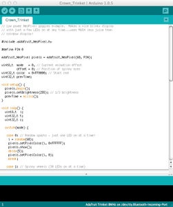

Before you attempt to upload software to the Trinket, I'd recommend reviewing the Adafruit tutorial. Make sure you have the proper software installed for your machine including drivers.
I am not much of a programmer and I am hoping with the public release of these plans that those who have mad programming skills with an artistic streak can create new programs for the laser crown. All I've done is remixed the Kaleidoscope Eyes code to fit the crown with my own rainbow mode and sparkly mode. It's still delightful to watch but there is so much potential here I can't wait to see what others can do with this project.
So back to Flashing the Trinket.
Run the Arduino software. Load the Crown Sketch.
Disconnect the Trinket from everything but the Micro USB cable and plug it into the computer.
If you haven't flashed the Trinket out of the box yet, the red LED should pulse. If it doesn't press the tiny button on top and release. You'll have about 5 secs to press upload on your computer to flash the AVR chip on the Trinket. If you missed the window, press it again and start over.
After the flash is complete, it should reboot with a green LED showing. Cool.
Attachments
Step 16: Test the LED Ring

Let's test the Neopixel ring. Once encased in the acrylic, it's very difficult to resolder broken connections so you want to make sure it works before continuing.
- Connect the Ring to the Trinket. (Wires match?)
- Connect battery to the Trinket. (Battery Charged?)
- Lights on Trinket blinking?
- Ring light up? All of them working?
You're good to go. Let's move on to construction.
Step 17: Gluing the Pocket


For the first two or three crown attempts, I didn't think it was important regarding the order of construction. Turns out, I recommend hot gluing on the pocket first. The Neopixel ring and connector are already soldered in place on the ring but glue the notched felt on the bottom of the bottom ring first. Be sure not to get any glue in the acrylic notches. That might be a source of vane breakage when you install them. Make sure one of the felt slots is aligned with the wiring hole so the wires will nicely enter the pocket and give you some access to adjust them if necessary.
Now for the hair clips, I don't know how many is really necessary but I had 6 slots and 6 clips so it will be ready for hurricane force winds.
Then glue the top of the pocket from the other side. Again place the slit on top towards the wiring. I tried to make it so it tucks in the top so don't glue all the way around the perimeter. You want some access to the inside.
Almost there...
Step 18: Construction


Stack both acrylic rings. Align the Neopixels so they match up with the notches since the vanes will go over the Neopixels at that point. The width of the Neopixel is a little over 5mm and the vane is 3mm so I lit up the ring just to see where most of the brightness comes from and put the vane over the top of that point.
Start from the back with the smaller vanes.
Gently wiggle the vane over the Neopixel ring and carefully slide the ends into the aligned notches of both rings placed together. Go slowly there's no hurry. Sometimes the plastic needs to stretch a little. Acrylic seems to break with more sudden moves.
It should have a nice soft click and the bottom middle of the vane should be on top of the Neopixel. There's some variation in the height of the Neopixel ring + solder so it won't be perfect but should be aligned and solid enough that you can wear it.
I haven't done this myself yet but when you're satisfied with the alignment and electronics it wouldn't be a bad idea to glue them into place with a little bit of acrylic glue. It might make it a little more robust.
When you're all done, all the vanes are in place, light it up. Well done.
Step 19: Coronation


So there are no formals, no proms, no exciting events in our house this week. I just managed to cajole a few in the house to try it on or at least balance it on their heads just one more time. But we are headed to the SF Maker Faire this year so we hope to show off some nerd royalty.
It works better than I imagined which was rewarding enough. Everyone who hasn't seen it wants to try it on. Even some of the boys in the house are thinking about becoming princesses for Halloween because it's so cool! It sits nicely on the back of the head and with the clips won't fall off. It's light weight and if you want to get noticed, it succeeds.
Step 20: FAQ

Can I get the OpenSCAD code to modify the design to fit my cat?
Sure. Just message me through Instructables.
Will you laser cut me a set of acrylic parts to make my own crown?
Message me through Instructables but plan on around $40 for just the acrylic.
Will you solder and construct a crown for me really cheap?
Um, no. I don't really want to be in the manufacturing business.
What else can I do with this?
Maybe you want to create your own vane design. Maybe somebody wants to add an accelerometer, compass, GPS, Bluetooth LE, etc. Maybe you have some coding ideas for lights. Maybe someone will make a cat size laser crown. Thanks for your interest and vote for my project. Best of luck!

Runner Up in the
Arduino Contest

Third Prize in the
Full Spectrum Laser Contest

Participated in the
Jewelry Contest


