

Introduction: Laser Cut Pen Vice for Rotary Engraving


A friend needed to be able to hold a pen on her rotary engraver but after finding out the price of the commercially available vice ($500+ ), we decided we could make our own . Using some 3 mm plywood ,a scrap of 6 mm Acrylic sheet and half a handfull of hardware out of the junk drawer, we came up with a simple and cheap alternative.
Step 1: Materials and Tools
Parts List
3 mm Plywood Sheet 450 mm x 350 mm
6 mm Acrylic Sheet 200 mm x 100 mm
M6 x 70 mm Bolt & nut
2 pieces of 6 mm x 50 mm Bright Mild Steel Rod
12 x M3 x 20 mm Screws and washers
6 x 3 mm Nuts (Temporary Clamping for Jaw)
Wood Glue
Tools Used
Laser Cutter
2.5 mm Drill Bit
M3 Tap
M6 Tap
M6 Die
Bench Grinder and Wire Wheel
Electric Hand Drill
Design
See attached DXF file
Attachments

Step 2: Laser Cutting the Parts.


You will need to Laser cut the base of the vise and knob parts separately from 6 mm Acrylic as per the drawing . The rest can be cut from the 3 mm Plywood.
Note that the parts are numbered in the order they are layed up in.
Take care that the smaller pieces are oriented as per the drawing as they are not square.
Step 3: Preparing the Bolt & Guides


The bolt I used needed to have the thread extended to within 20 mm of the Head so as to obtain the required amount of travel.
Make sure to use a lubricant when doing this.
Using the Bench Grinder, machine the Hex head of the bolt so as to make it round. Wire Brush the head to remove any apparent roughness. I also wire brushed the thread to make it smoother to run the nut on.
Trim the 6 mm Rod to 50 mm long. Grind a small bevel on each of the ends and wire brush.
Step 4: Jaw Assembly


Assembling the Jaw
the Jaw consists of the pieces in the upper left of the picture.
Insert 6 Screws through Jaw part labelled 1.
Apply a small amount of glue to part 2 and fix to Part 1
Follow the same for jaw parts 3 and 4.
Insert the bolt as per the pic and complete gluing up the rest of the Jaw parts
Ensure that the openings for the guide rods are free of any excess glue and squarely aligned.
Fit each bolt with a nut, tighten and allow the glue to set.
Step 5: Base Assembly


Drill the holes in the Acrylic base to 2.5 mm and Tap to M3.
I used the electric drill to tap the holes - driving the Tap through and reversing back out again. Clean any of the Acrylic swarf off the Tap before reversing to avoid pinning.
Remove the Nuts and Screws from the Jaw assembly when cured.
Assemble the rest of the Base parts using the same numbering system as the Jaw in reverse with the Acrylic Base being Part 6.
Apply the Nut to the Bolt and run it down about 1/2 way
Insert the Guide Rods into the jaw and add to the stack of base parts. The Nut should be fitted into its recess on the frame as should the guide rods into theirs.
Complete laying up the rest of the base by the numbers and then screw to the Acrylic base using a washer on the M3 screws.
Tap the 3 pieces of acrylic knob to M6 and tighten them against each other on the Bolt to create a knob.
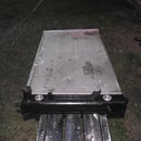
Step 6: Finished

Thats it.
Total cost - less then $5....
Design time - 3 or 4 iterations - couple of hours
Manufacturing Time - 40 minutes

Participated in the
Woodworking Contest


