

Introduction: Lego Nerf Arduino Turret


The inspiration behind this project came from a desktop turret they sell at staples, and a couple servos I had lying around. Many a time I have been told that Lego's are no good for building something serious (like a robot), so hopefully they will be proven wrong.
Step 1: Make a Plan


The turret will need at least to servos two pan and tilt, a servo for the trigger, a ton of legos, and an arduino. However the specifics can vary quite a bit. Especially when it comes down to the legos.
This turret calls for:
1.) two HS-322HD servos --- $9.99
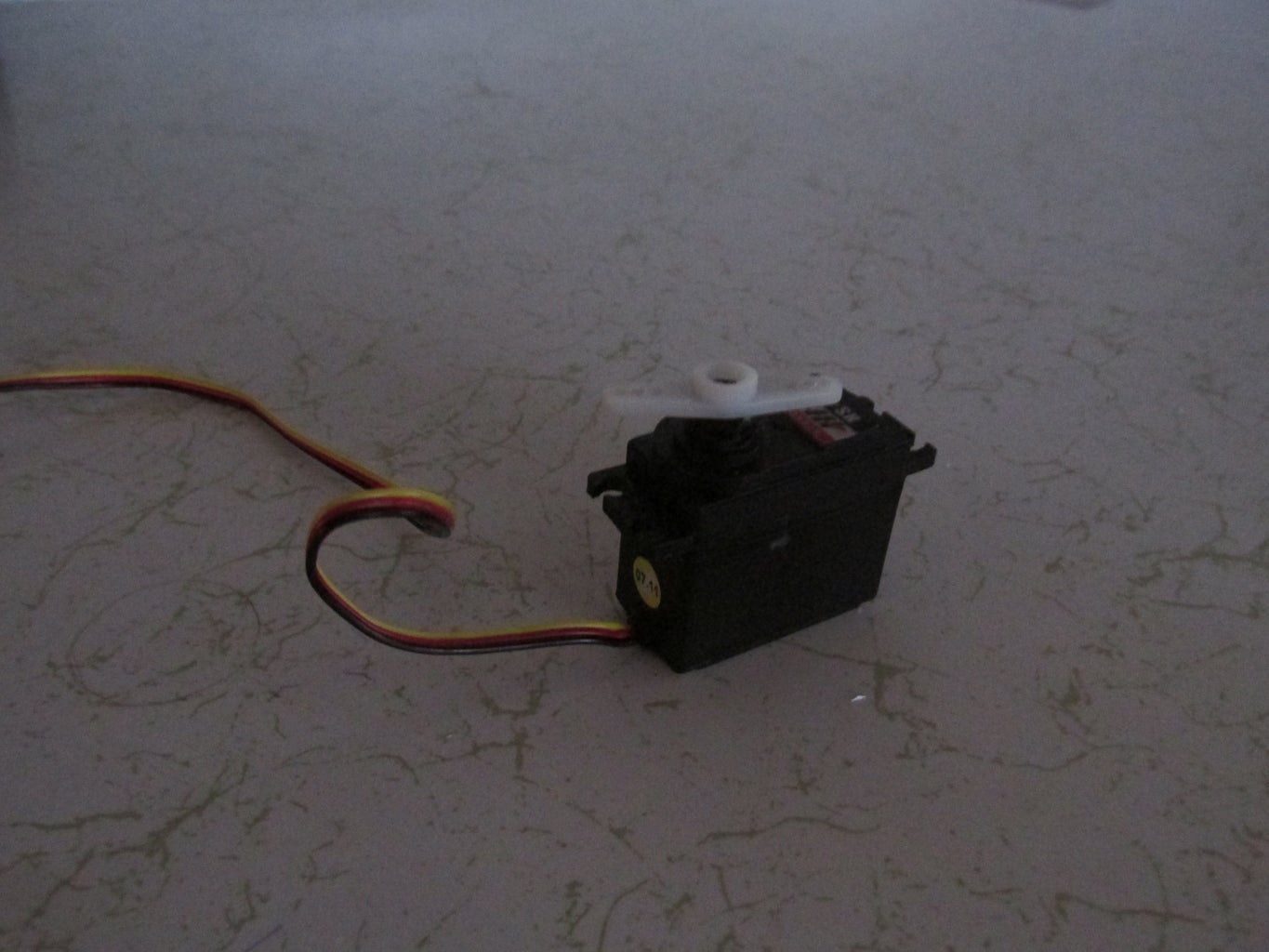
2.) a small servo of any variety --- $8.95
3.) an Arduino Uno --- $25
4.) Nerf Gun --- $6 this is a Nerf reflex. This one works great because of small size and flat side for gluing)
thanks to nerfrocketeer for gun name and price
but make sure to have:
1.) Plastic Epoxy --- $5.50
2.) a Computer
3.) a Box of Legos
4.) PS1 controller
5.) PCB board and Breadboard
6.) also there will be some soldering and desoldering
So all in all it should cost about $50 if you have Legos
This project is pretty tough and took about four whole afternoons to build so it will take a while. Be ready to commit to it (plus you will have to ruin some precious Legos :( ).
Step 2: Build the Frame


Now where you go after you get everything you need is really up to you. From here the project may split to building the turret, or maybe create the code so if you would rather play with the servos and Arduino first go for it!
However, here is how build the turret first. To allow the gun to tilt, the gun and a servo have to be floating and only connect to the rest of the structure by a servo, and a point opposite and parallel to the servo that can freely turn. The structure will still need support so build a frame!
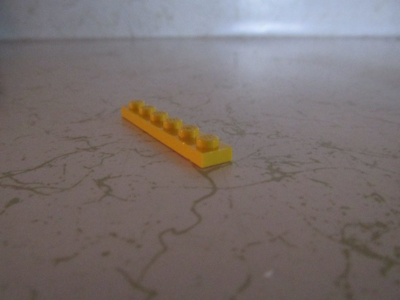
Using 2 X 3 Lego bricks make a the outline of a square or rectangle two bricks high. The size is dependent on the nerf gun so use it as a guide ( make the frame a little bit bigger than the gun). servo is much easier to convert into a Lego than you would think. The 1 X ? bricks will glue perfectly into the
HS - 322 and allow it to connect to the frame.
On the opposite side of the servo, two bricks with a hole and an axle can be used to connect the frame and the nerf gun without restricting rotation.
Step 3: Preparing and Gluing the Gun


To turn a nerf gun into a lego brick takes some work.
with the n - strike attack gun I used it was pretty straight forward. First remove the hand grip which is just three screws.
Clean off one side with rubbing alcohol, making sure that one side is not the one with the screws because you might want to get on the inside of the gun later (I cut down the spring so it wouldn't fire so violently).
Next, pick the bricks that will be sacrificed - the more, the better. Two columns of 2X2 bricks 5 long should be enough, so take a flat piece and connect all the bricks into it, cover them in epoxy (wear gloves and protect surface), and then place the gun on the glue. Once again, try not to make it impossible to get into the inner workings of the gun. Put some weight on top of the gun like a rock, and let it dry for a day, don't worry there is plenty more to do. (consider checking out step seven)
Step 4: The Trigger Servo


A Smaller Servo is Needed Here:
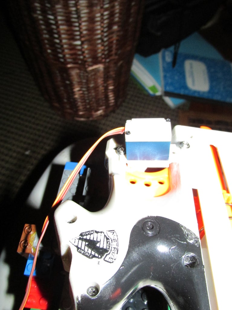
It should wedge just great into the trigger guard, but also consider cutting or sanding away a little grove for it to make a snugger fit (in picture it is held down by epoxy and a screw).
An Extra Note:
For the servo to actually pull (in this case push) the trigger it may be necessary to add some thickness to whatever blade is on the servo. So put a screw or bolt through it.
Step 5: Install the Gun


After the Glue Drys :
Create a platform out of plank pieces that will fit well in the space of the frame, the gun which is now a modified lego brick can be attached.
To attach the servo, simply place some lego pieces down, mark a few points, pre-drill, and screw the servos in.
The HS - 322 seem to work well if left a five point gap, as can be seen in the picture above.
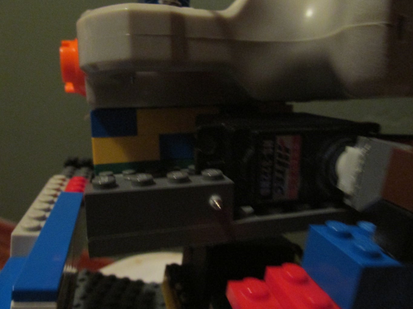
Step 6: Pan Servo


Pan Servo Time:
Screw the pan servo into some 1X8 bricks... one per side and make sure the connections are pointing away from the white connector.
To help strengthen it up use a couple plank pieces to hook the 1X8's together, and then use whatever combination of bricks you'd like to connect this to the bottom of the frame.
The servo can connect to any large lego piece on bottom the same way the tilt servo worked, a plank piece with single width (I went with a 1X2 plank for this).
this bottom piece will be the base so make sure it is large, heavy, and stable.
A Note on Placement of the Servo:
It may not be best for it to be perfectly centered so consider your center of mass with the frame and gun platform, and place the servo directly under that.
Step 7: PS1 Controller Desoldering
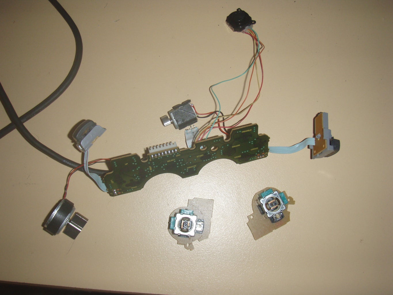
thanks to blaze3927 from benheck.com Forums because I took my controller apart a long time ago and this picture is perfect.
Once you rip apart your precious ps1 controller you will see the joysticks, they are on there own little boards. Each one is attached by six pins for use in the joystick, and a couple structural ones.
Step 8: Ps1 Joystick ... All Wired Up
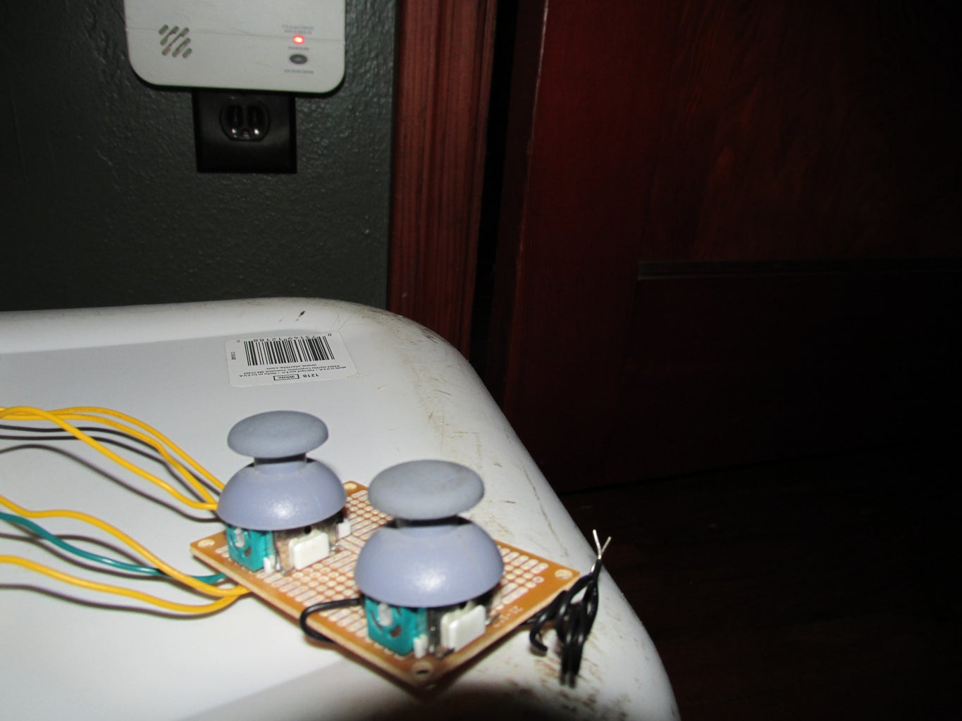

The middle pin is signal the outside being positive or negative for both the pot's on the joystick. To test it out just give one outside pin 5v's, the other outside ground, and the middle goes to an analog pin on the Arduino. Fire up an example and have fun.
Consider soldering the joystick to a piece of pcb like what it was found on to make it look a little nicer.
Also remember that when bread boarding to pot's you can use the same ground pin but you will want to use two pins to power them (they are resistors and change the voltage when moved, if in series one effects others signal).
Step 9: Breadboard!!


Already described the potentiometers.
The servos can have different colors of wires but they all mean the same three things... Power, Ground, and Signal. Check this link out if you need any help.
Servos can share the same power and ground which helps out with the wiring.
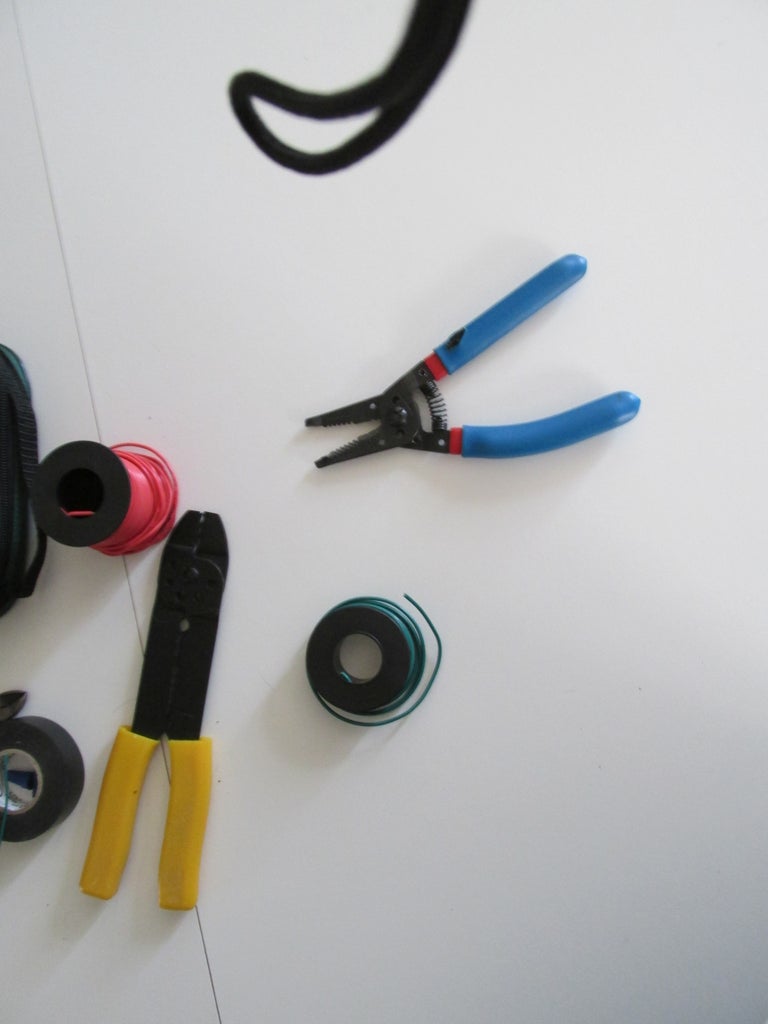
Don't forget to use 22 gauge wire anything larger size, smaller gauge can ruin the holes in breadboard or Arduino.
Step 10: Code... Almost Done!

First is a chunk used for the trigger
#include <Servo.h>
Servo myservo; // initiate an instance of Servo class
byte byteRead;
int pos = 0;
void setup() {
// Turn the Serial Protocol ON
myservo.attach(3);
myservo.write(0);
Serial.begin(9600);
}
void loop() {
/* check if data has been sent from the computer: */
if (Serial.available()) {
/* read the most recent byte */
byteRead = Serial.read();
/*ECHO the value that was read, back to the serial port. */
if (byteRead = 'F');
{Serial.println("fire");
for(pos = 0; pos < 120; pos += 1) // goes from 0 degrees to 180 degrees
{ // in steps of 1 degree
myservo.write(pos); // tell servo to go to position in variable 'pos'
delay(15); // waits 15ms for the servo to reach the position
}
for(pos = 120; pos>=1; pos-=1) // goes from 180 degrees to 0 degrees
{
myservo.write(pos); // tell servo to go to position in variable 'pos'
delay(15); // waits 15ms for the servo to reach the position
}
}
}
}
Next is the full on code for the turret, keep in mind to fire this you type F into the serial port that is what the above code tests.
There are also commented out Serial.println() lines of code. If yuncommented they can be used to debug and gather numbers from pot's.
#include <Servo.h>
/* by Gabe Magnuson
for: Lego Nerf Arduino Turret
7/24/2013
*/
/*
boot this up and test the range of numbers on your analog stick,
my ps1 stick values ranged from 0 - 1000 and set them as sensorMin and sensorMax
also check to make sure all servo pins and pot pins are correct
*/
const int numReadings = 10; // const cannot be changed
const int sensorMin = 0; // minimum value of analog stick, test for it using serial terminal
const int sensorMax = 1000; // maximum value of analog stick, test same way
byte byteRead;
Servo servo1; // start an instance of the servo and give it a name
Servo servo2;
Servo servoFire;
int pos = 0;
int servo1Readings[numReadings]; // the readings from the analog input
int servo2Readings[numReadings];
int index = 0; // the index of the current reading
int servo1total = 0; // the running total
int servo1Average = 0; // the average
int servo2total = 0; // the running total
int servo2Average = 0; // the average
int pos1 = 90;
int pos2 = 90;
int pos1Old = 90;
int pos2Old = 90;
int inputVertical = A0; // input pins for pot's signal wire
int inputHorizontal = A1;
int sensorRange = 0; // variables used to decide the range for movement
int topRange = 0;
int bottomRange = 0;
void setup()
{
pinMode(OUTPUT,A5); // initialize these pins as outputs to power analog sticks
pinMode(OUTPUT,A4);
pinMode(INPUT,inputVertical); // set pin for pots to input
pinMode(INPUT,inputHorizontal);
Serial.begin(9600); // initialize serial communication with computer:
for (int thisReading = 0; thisReading < numReadings; thisReading++) // initialize all the readings to 0 in both arrays (to smooth values, if confused checkout "smoothing" at arduino website)
{servo1Readings[thisReading] = 0;
servo2Readings[thisReading] = 0;}
servo1.attach(10); // this is A2, the numnering from the digital pins continue to the analog starting at A0
servo2.attach(11); // this is A3
servoFire.attach(16);
sensorRange = sensorMax - sensorMin; // this chops the range of the pots into six chunks and then takes the top and bottom 2 to be used in the motion of the servos
sensorRange = sensorRange / 6;
bottomRange = sensorRange * 2;
topRange = sensorMax - bottomRange;
servoFire.write(0);
servo1.write(90);
servo2.write(90);
}
void loop() {
pos1Old = pos1; // keeps pos from changing if no movement is detected
pos2Old = pos2;
analogWrite(A5,168); // these two pins are used to power analog sticks
analogWrite(A4,168);
digitalWrite(12,HIGH);
// subtract the last reading:
servo1total= servo1total - servo1Readings[index]; // smooths data coming from pots
// read from the sensor:
servo1Readings[index] = analogRead(inputHorizontal);
// add the reading to the total:
servo1total= servo1total + servo1Readings[index];
// calculate the average:
servo1Average = servo1total / numReadings;
// subtract the last reading:
servo2total= servo2total - servo2Readings[index];
// read from the sensor:
servo2Readings[index] = analogRead(inputVertical);
// add the reading to the total:
servo2total= servo2total + servo2Readings[index];
// advance to the next position in the array:
index = index + 1;
// if we're at the end of the array...
if (index >= numReadings)
// ...wrap around to the beginning:
index = 0;
// calculate the average:
servo2Average = servo2total / numReadings;
if (servo1Average > topRange)
{pos1 ++;
if (pos1 > 180)
{pos1 = 180;}
//Serial.println("servo1 up");
}
else if (servo1Average < bottomRange)
{pos1 --;
if (pos1 < 0)
{pos1 = 0;}
//Serial.println("servo1 down");
}
else
{pos1 = pos1Old;
//Serial.println("servo1 nowhere");
}
if (servo2Average > topRange)
{pos2 ++;
if (pos2 > 110)
{pos2 = 110;} // limits servo movement
//Serial.println("servo2 up");
}
else if (servo2Average < bottomRange)
{pos2 --;
if (pos2 < 75)
{pos2 = 75;} // limits servo movement
//Serial.println("servo2 down");
}
else
{pos2 = pos2Old;
//Serial.println("servo2 nowhere");
}
/*Serial.println(pos2); // you can use this bit to debug and track what degree the servos are set to
Serial.println(pos1);*/
servo2.write(pos2);
servo1.write(pos1);
/* check if data has been sent from the computer: */
if (Serial.available()) {
/* read the most recent byte */
byteRead = Serial.read();
/*ECHO the value that was read, back to the serial port. */
if (byteRead = 'F');
{Serial.println("fire");
for(pos = 0; pos < 120; pos += 1) // goes from 0 degrees to 120 degrees
{ // in steps of 1 degree
servoFire.write(pos); // tell servo to go to position in variable 'pos'
delay(15); // waits 15ms for the servo to reach the position
}
for(pos = 120; pos>=1; pos-=1) // goes from 120 degrees to 0 degrees
{
servoFire.write(pos); // tell servo to go to position in variable 'pos'
delay(15); // waits 15ms for the servo to reach the position
}
}
}
/*Serial.println(analogRead(inputVertical));
Serial.println(analogRead(inputHorizontal));*/
// this can be used to test the min/max of pots
delay(5); // delay in between to give servo time to move
}
Step 11: Have Fun
Thanks for reading... If the community has any coding or bread boarding tips, they would be very welcome!

Participated in the
Toy Building Blocks Contest

Participated in the
Arduino Contest


