

Introduction: Let's Make! 5 More BreadBoard Projects for Beginners


With the previous version of this instructable (10 Breadboard Projects For Beginners) hitting more than 300K views and getting a lot of positive feedback from people, I decided to have one more 'How To' with more awesome projects! So here's presenting you 5 More Breadboard Projects For Beginners..
Following the same concept as the previous one, I always aim it to be learning experience for both you and me. If you are not too experienced with soldering or printed circuit boards or etching, then this is perfect for you. Well breadboards, were made mostly for prototyping, but you can use them to experiment and learn through temporary projects. This is just to help you get started with electronics and give an intro to basic components/the way they work. After trying these, you can move on to micro controllers and try a few difficult projects.
Here's a list of the five projects you'll be learning here:
- Project 1: Firefly
- Project 2: Alternate Flashing LED Lights
- Project 3: MultiColor LED Lights (w/ an RGB LED)
- Project 4: Traffic Lights
- Project 5: Fastest Finger First (Game)
Want to interact, leave suggestions/feedback and share your ideas?
Just leave a comment below or contact me at saiyamagr@gmail.com
________________________
Here's a video of all the projects in action:
Do Subscribe to my YouTube channel as well.
Step 1: First Things First

You avoid any confusion, I clearly specify that I do not hold the copyright of any schematic or projects mentioned in this instructable. The circuits were obtained from different websites (which is mentioned after every project). The schematics were re-made using the Fritzing library to make them more neat and readable. The breadboard layouts have also be made using the same software.
This was just an attempt to share a guide to help beginners work with simple circuits. My intention is never to copy someone's work (I am still 16, and a student so there's not much complexity involved here).
I got a lot of criticism (constructive, luckily) along with appreciation in the previous version. Expecting the same here. Please feel free to help me make this instructable and future projects better.
Step 2: Some Notes About Breadboard
The content below gives you a brief description of breadboard before you proceed towards attempting the projects. The matter has been copied from the previous instructable with some edits.
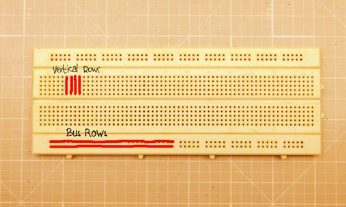
So Breadboard is a base for constructing (more for prototyping) electronic projects. It can be a great option for beginners with the purpose of creating easy and temporary projects without the need to solder the components. It is a great way to construct temporary projects as almost all the components can fit smugly (not the ones with thick leads) in the holes. It has mainly two types of rows- bus rows or horizontal rows and vertical rows.
Bus rows or horizontal rows are used to connect power or a battery to a breadboard. There are a total of four bus rows in a breadboard- two in the uppermost part while two in the lower part. In a 840 points breadboard, a divider is present in each row when halfway of a row is completely. Usually these dividers are connected through hookup wire to easily connect the power lines to the vertical rows. Bus rows are also called the power rails of the breadboard.
Vertical rows are another type of rows where most of the electronic components are connected. There is a large gap in the middle of the breadboard where the connection between the vertical rows is broken. This place mainly holds integrated circuits (ICs). Since the connection is broken here, each vertical row is connected to its respective pin of the IC where components are added. Vertical rows are connected to bus rows wherever power is needed.
Breadboards are available in various shapes and sizes to meet the needs of a project. They also have grooves through which they can be inter-connected to each other to make bigger breadboards. A special type of wire called hookup/jumper wire is used to make connections in a breadboard. Using other types of wires can damage it.
More details: How to: Breadboard
Step 3: Some Notes About Different Electronic Components

As with the previous instructable, I have provided a brief intro to some of the very basic electronic components which will be used to build the projects.
(1) Resistor:
So a resistor is a device that reduces current in a circuit by offering obstruction to the flow of electrical current. So if you connect an LED directly to a 3v battery and then connect it by adding a resistor in series, the brightness in the second case would be lower than the first one as the resistor in the second case would not allow much current to pass through, thus reducing the brightness. Resistance is normally measured in ohms, kilo ohms and mega ohms.
(2) Capacitor:
A capacitor is a device that stores electricity inside it when it is supplied and gives it out in a circuit when there is a loss in electricity. It is like a rechargeable battery but there is a lot of difference between them. A capacitor can store a small amount of current and can charge instantly whereas a battery can store a large amount of current and takes a while to charge. There are many types of capacitors but the two common types are- electrolytic (polarised) and non electrolytic (non polarised). Capacitance is normally measured in pico farads, nano farads and micro farads.
(3) Transistor:
A transistor is a device that amplifies a small current applied on its base pin to produce a large current that flows between the collector and emitter pins. It does not create a large current but acts as a switch which when supplied a small current on the base pin, closes the switch (switches it on). There are two types of transistors- NPN and PNP.
(4) Integrated Circuit (IC):
An integrated circuit is a small package that is made for a particular task. It has a miniature inbuilt circuit that has many components inside it can perform a particular task. For example- a 555 IC is meant for timing circuits and LM386 is meant for amplifying audio signals. It is usually a small black chip with pins coming out from the package. There are 3 pin ICs as well as 32 pin ICs and even more.
(5) Diode:
A diode is a device that allows current to flow only in one direction. This is the reason it has polarity and should be connected correctly for its proper functioning. It is used to prevent the reverse flow of current.
(6) Light Emitting Diode (LED):
A light emitting diode is a special type of diode that can emit light when electricity is passed through it. Like a diode, an LED also allows current to flow only in one direction so to make it work it should be connected properly in a circuit. These days LEDs are preferred over lightbulbs as they consume much less electricity than bulbs and CFLs. They are available in different shapes, sizes and colors but being energy efficient, their cost is much high.
More Details: Instructable- Basic Electronics
Step 4: Parts and Tools Required

The parts and tools required for attempting all the projects have been mentioned below. Many people in the previous I'ble inquired about stores where these parts can be obtained from. So I have mentioned below some of the sites where they can be bought. The total cost may vary as per your source. I just got them from my local electronics store, thus it summed up to approx. $8.
You can also buy assortment kits, consisting of all the parts required here. Such as this.
Buy this awesome breadboard starter kit online: KEYES KT0053 Electronic Component Package
Resistors can't be bought online separately. Hence you can buy this Resistor Pack which contains all the values used here.
Similarly, this Electrolytic Capacitor Set with 12 different values.
And this Non-Electrolytic Capacitor Set.
____________________
Parts:
1) Integrated Circuits:
- 2x NE555
- 1x 74HC14
- 1x CD4017
2) Resistors:
- 4x 10K ohm
- 3x 100K ohm
- 2x 1K ohm
- 1x 1M ohm
- 3x 100 ohm
- 1x 47K ohm
- 1x 22K ohm
3) Capacitors:
- 2x 10uF
- 3x 22uF
- 1x 1uF
- 2x 0.1uF
4) Other:
- 6x LEDs (or more)
- 1x RGB LED
- 6x IN4007 or 1N4148 Diodes
- Hookup wires
- 3x Momentary push buttons
- BreadBoard (of course :P)
Tools:
- Wire cutter
- Wire Stripper
- Pliers
- A 5v Power supply (an adaptor or a power bank)
Step 5: Preparing the Power Rails of BreadBoard


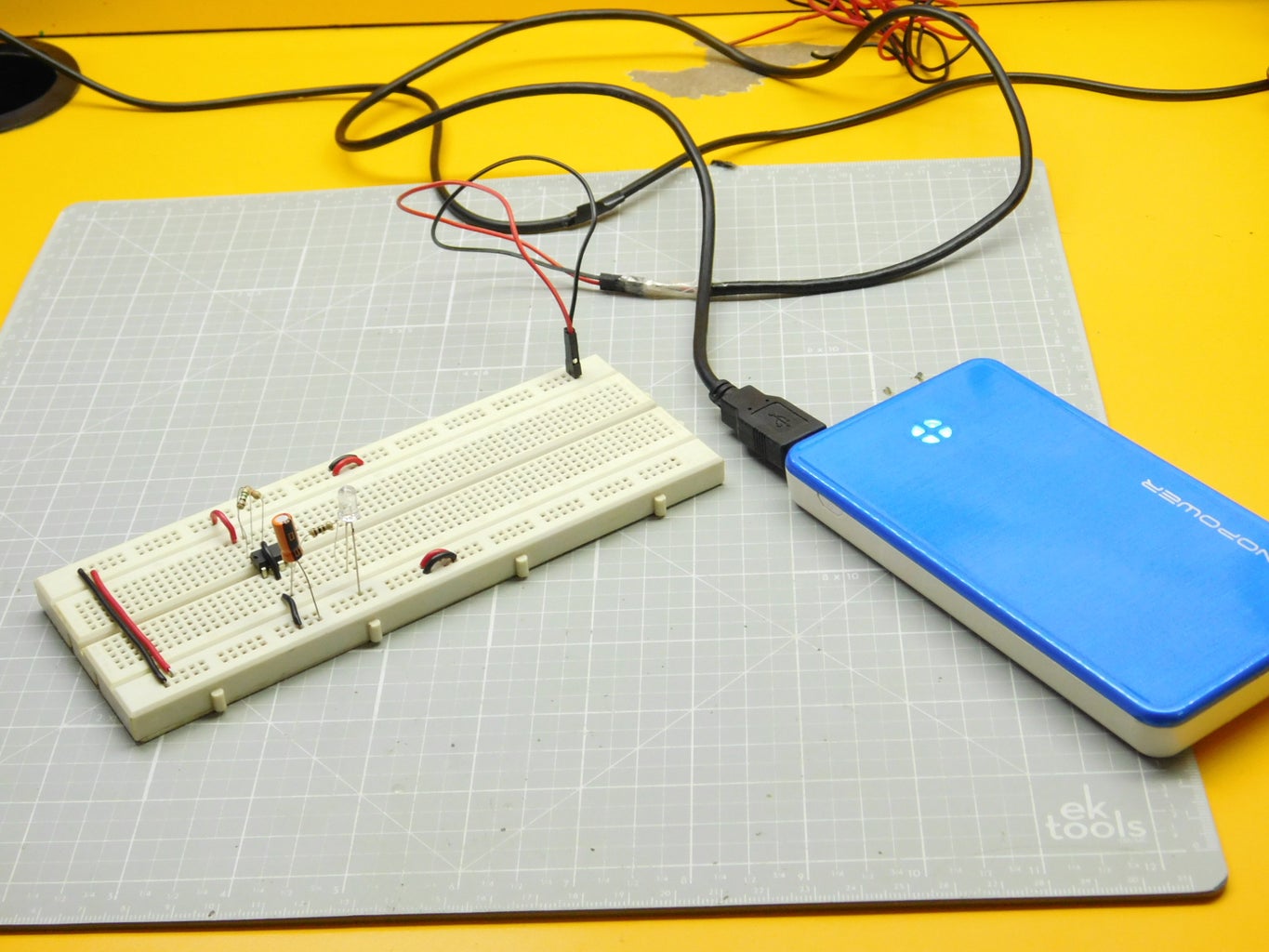
Now done with the boring (theory) part, you will have to first make some minor connections and choose a power supply for all of your projects. This is similar to Step 4 of my previous instructable, except that we would be using a power bank instead of a 9v Battery as some people pointed it there.
First you'll have to make some simple connections (refer the layout above) using jumper wires. Just use the required length and strip off both the ends using a wire stripper. Use different colors of wires to avoid confusion.
The next step is to take a random USB cable (should not be damaged). Cut off the other end of the cable as shown above. On stripping off the insulation, you will notice a Red, a Black, a White and a Green wire. Leaving the black and red ones, cut the rest as they won't be needed. Now connect each one of the remaining wires to a jumper wire. These will act as the positive and negative terminals. Connect the Red wire to Positive rail of the breadboard and black one to the negative rail. Now the USB port can be connected to any suitable power source (like a wall adapter, laptop or power bank). I chose the last option, being portable and small.
Step 6: Project 1: Firefly


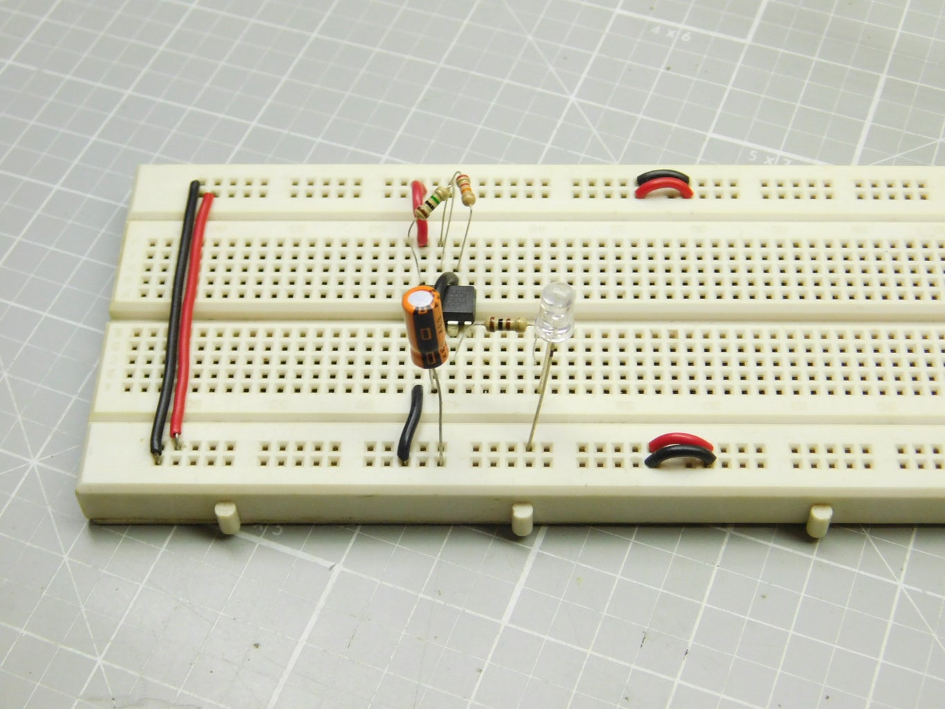
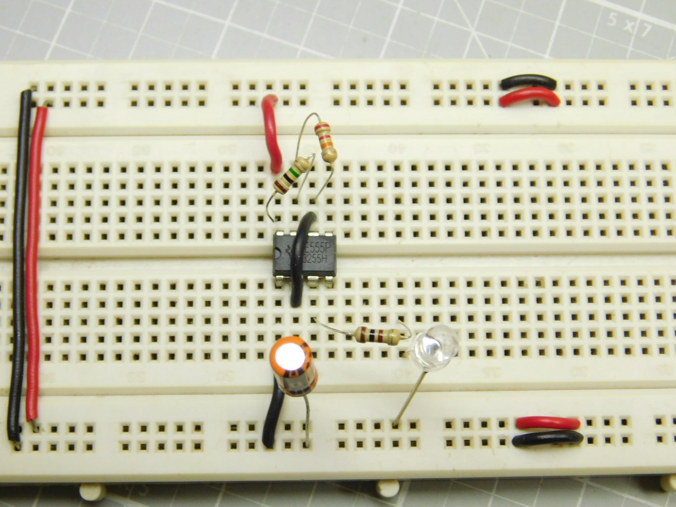


The very first project presents you an LED that glows after every fixed amount of time (like fireflies do). The connections are quite easy, provided you know the pin configuration of the IC used- The 555 timer. So this is an 8 pin Integrated Circuit used for timer, pulse generation and oscillator applications. In this project, it is acting has an astable multi-vibrator, producing pulses that depend on the values of capacitors and resistors connected in the circuit. The output stays high for a time based on the 1M resistor plus the 22K resistor as the capacitor charges, then goes low for a short time based on the 22K resistor discharging the capacitor. Of course, the blinking frequency can be varied, by changing the 10uF capacitor value from 4.7uF to 100uF.
I will not give in-depth explanation to the workings of the circuit, as you may learn more after attempting all the projects and referring different articles and blogs all over the internet.
Connect everything as per the BreadBoard layout given above. You can also refer the schematic diagram if it doesn't work in first attempt. Use proper jumper wires for good electrical contact. After connecting everything, connect an appropriate power supply. The LED would now glow every 5-6 seconds. Try changing the values of the 1M/22K Resistors and the 10uF Capacitor, now see the change in the delay.
Difficulty: Easy
Parts Used:
- 1x NE555 IC
- 1x LED (any color)
- 1x 10uF Capacitor
- 1x 1M ohm Resistor
- 1x 100 ohm Resistor
- 1x 22K ohm Resistor
Circuit Source:https://www.instructables.com/id/The-555-FireFly/
'How To' Video:
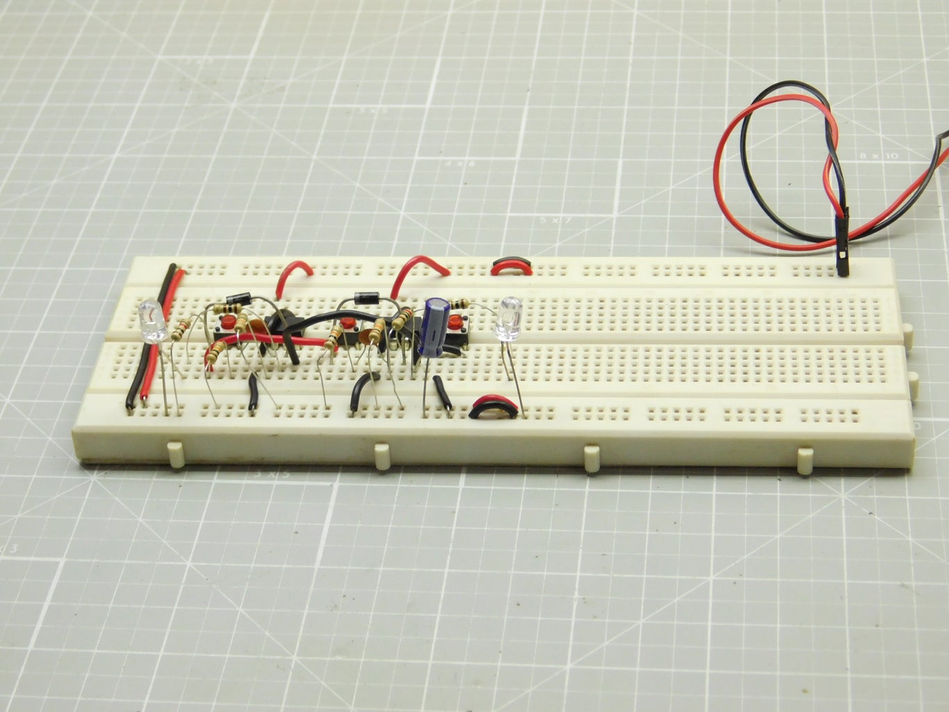
Step 7: Project 2: Alternate Flashing LED Lights


The next project describes two LEDs that flash alternately over a fixed interval of time. So again we're using a 555 timer IC here, in astable mode. The resistor/capacitor values are such that the output on pin 3 switches between low to high. You may see in the schematic that the positive terminal of one of the LEDs is connected to pin 3 via a resistor while the negative terminal of the second LED is also connected to the same pin. Thus, when the output is 1 (High), LED 1 glows and when the output is 0 (Low), LED 2 glows. The cycle continues.
Connect all the components as per the layout. At last, connect a power supply and check if it works. You have to be very accurate with the connections. Try changing the value of the 47K resistor to random. Decreasing the value would increase the flashing speed.
Difficulty: Easy
Parts Used:
- 1x NE555 IC
- 1x 10uF Capacitor
- 2x LEDs (any color)
- 2x 100 ohm Resistors
- 1x 47K Resistor
Circuit Source:Learning About Electronics
'How to' Video:
Step 8: Project 3: Multicolor LED Lights (w/ RGB LED)


This one's a bit interesting. So an RGB LED is connected to a 74hc14 IC known as the Hex Inverting Schmitt Trigger, commonly used as wave/pulse shapers and multivibrators. There are a total of 6 inputs each with an output. As the RBG LED has three colors, we would be using only 3 of them. The circuit is designed in such a way that the input level changes automatically which results in random output in all the three pins, thus producing different colors (a variety of colors can be produced by mixing the three primary ones through an RGB LED).
You may want to see the pin configuration of the IC which is given above. Pin 7 is always connected to Gnd while 14 is connected to Vcc. Carefully make all the connections according to the layout. Power the circuit and you'll see the LED displaying random colors. You may also try experimenting with different resistor/capacitor values and notice the change. You may fail sometimes, but never stop tinkering.
(Note that I used two 10uF capacitors connected to pin 5 instead of one 22uF due to unavailability. They are connected in parallel, so final value is the sum of both.)
I has to be checked whether you are using a common anode or a common cathode LED. The above circuit is only for common cathode. For the anode type, just connect the common terminal to Vcc and R,G,B terminals to their respective output pins.
Difficulty: Easy
Parts Used:
- 1x 74hc04 IC
- 1x RGB LED (I prefer common cathode type)
- 3x 22uF Capacitors
- 3x 100K ohm Resistors
- 3x 100 ohm Resistors
Circuit Source:30 LED Projects by Talking Electronics
'How To' Video:
Step 9: Project 4: Traffic Lights


The fourth project will introduce the 4017 counter IC along with the 555 timer, to make these cool automatic timer controlled Traffic Lights. The 555, again is wired in astable mode, which produced pulses of specific frequency. These pulses are then sent to the 4017 which counts them, and sets the first pin High. On successive pulses, it makes all the pins high one by one then again starts from zero. You may see in the circuit that the maximum number of pins are connected to the green LED, which means that it will glow the longest. On the other hand, the red one will glow the shortest. Diodes are added here to prevent reverse flow of current into the output pins.
The pin configuration of 4017 can be found above. You must connect everything as per the layout. Power up the project and see if it works. Again, you may experiment with the capacitor and two resistors connected to pins 6,7,8 to vary the timing of each light. Try connecting more number of output pins to the yellow LED instead of green and notice the variations.
Difficulty: Medium
Parts Used:
- 1x NE555 IC
- 1x CD4017 counter IC
- 1x 10uF Capacitor
- 1x 0.1uF Capacitor
- 3x LEDs (Red, Yellow/Orange, Green)
- 3x 100 ohm Resistors
- 2x 100K Resistors
- 1x 22K Resistor
- 6x IN4007 or 1n4148 Diodes
Circuit Source:CircuitEasy
'How To' Video:
Step 10: Project 5: (Game) Fastest Finger First


That's the last, and the most interesting of the projects (or rather a game). The aim is to press the button earlier than your opponent (w/ 2 players). A third person would be there to reset the switches and to restart the game.
One more use of this is, as a Quiz timer. Whichever competent knows the answer, has to quickly press the buzzer, which will lead to disability of other buttons. Even if both the players press the buttons at the same time, this circuit can decide between fractions of milliseconds.
You have to be careful with the circuit, as this one has quite messy connections. Use up the entire breadboard space to make it more neat. Finally power up the circuit and press one of the two buttons, the corresponding LED would light up. You will also notice that pressing the other one would now do nothing. Press the reset button to start the game again.
How To Increase The Number of Players? Well, you can have as many as you want! More details here.
Difficulty: Hard
Parts Used:
- 2x NE555 ICs
- 2x LEDs (different colors)
- 3x Momentary push buttons
- 4x 10K ohm Resistor
- 2x 1K ohm Resistor
- 2x 100 ohm Resistor
- 1x 1uF Capacitor
- 2x 0.1uF Capacitors
- 2x IN4007 or 1N4148 Diodes
Circuit Source:Engineers Garage
'How To' Video:
Step 11: The End..

So that's the end of this instructable. Hoping that this was a learning experience for you. Even if you're aware of the basics, you can leave some suggestions or improvements below.
You may also start working with more complex circuits and go to an in-depth explanation to all of them. Some of the 'must visit' websites are:
If you want more such instructables to be published, do mention it in your comment.
Thanks for watching..
Happy Making :)

Participated in the
Maker Olympics Contest 2016

Participated in the
LED Contest


