

Introduction: Light Following Robot Using Arduino
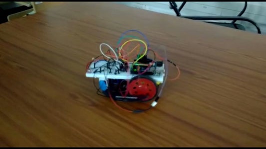


Hi everyone. creating a robot that follows the light you are giving as input is simple . we create this project using arduino and three LDR that are mounted in front, left side and right side. we give light input to any of these ldr's and the robot detects the light and follows it. The program and other instructions are provided below.
MATERIALS USED:
- arduino uno
- LDR - 3
- 9v battery 2
- dc motor 2
- bread board
- connecting wires
- chassis
- l293d motor driver
Step 1: Using L293d Motor Driver Ic

L293d motor driver connections are as shown in picture
- the 1st and 9th pins are enable pins they always should be given HIGH. connect it to 5v
- pins 4,5,12,13 are ground connect it to the ground
- pins 2 and 7 are inputs for the left motors connect this pins to the arduino gpio pins
- pins 10 and 15 are input pins for right motor connect it to the arduino gpio pins
- pin 8 is vcc pin that is we should give the batteries positive to vcc and ground should be connected to the ground
- pin 16 we can connect it to 5v
- pins 3 and 6 are output pins for motor connect it to the left motors wire
- pins 11 and 14 are output pins for right motor connect it to the right motor wires
CHECK THE MOTORS WORKING:
code given below is to check the working of motor alone:
int input1leftmotor=7;
int input2leftmotor=3;
int input3rightmotor=2;
int input4rightmotor=4;
void setup() {
pinMode(input1leftmotor, OUTPUT);
pinMode(input2leftmotor, OUTPUT);
pinMode(input3rightmotor, OUTPUT);
pinMode(input4rightmotor, OUTPUT); // put your setup code here, to run once:
}
void loop() {
digitalWrite(input1leftmotor,HIGH);
digitalWrite(input2leftmotor,LOW);
digitalWrite(input3rightmotor,HIGH);
digitalWrite(input4rightmotor,LOW); // put your main code here, to run repeatedly:
}
Step 2: Connecting the LDR

the circuit above is to connect the ldr with arduino . our project uses 3 ldr, so connect the 3 ldr's one in front of the robot, others in left and right. make sure the connections are correct. for further checking upload the code below and check whether the 3 ldr's are working correctly. close 2 ldr and see if other ldr show higher value or the other 2 closed ldr's show less value,..code is given below
int ldr1center=A0;
int ldr2left=A1;
int ldr3right=A2;
void setup() {
pinMode(ldr1center, INPUT);
pinMode(ldr2left, INPUT);
pinMode(ldr3right, INPUT);
Serial.begin(9600); // put your setup code here, to run once:
}
void loop() {
int value1=analogRead(ldr1center);
int value2=analogRead(ldr2left);
int value3=analogRead(ldr3right);
Serial.print("value1=");
Serial.println(value1);
delay(2000);
Serial.print("value2=");
Serial.println(value2);
delay(2000);
Serial.print("value3=");
Serial.println(value3);
delay(2000); // put your main code here, to run repeatedly:
}
Step 3: Final Step Code
connect all the wires in a single breadboard the code will be as follows
int enablepin1=11;
int enablepin2=12;
int input1leftmotor=2;
int input2leftmotor=4;
int input3rightmotor=7;
int input4rightmotor=3;
int ldr1center=A0;
int ldr2left=A1;
int ldr3right=A2;
void setup() {
pinMode(input1leftmotor, OUTPUT);
pinMode(input2leftmotor, OUTPUT);
pinMode(enablepin1, OUTPUT);
pinMode(input3rightmotor, OUTPUT);
pinMode(input4rightmotor, OUTPUT);
pinMode(enablepin2, OUTPUT);
pinMode(ldr1center, INPUT);
pinMode(ldr2left, INPUT);
pinMode(ldr3right, INPUT);
delay(2000);
Serial.begin(9600);
}
void loop() {
int value1=analogRead(ldr1center);
int value2=analogRead(ldr2left);
int value3=analogRead(ldr3right);
if (value1>value2&&value1>value3) {
straight();
delay(1000);
Serial.println("straight");
}
else if (value2>value1&&value2>value3) {
left();
Serial.println("left");
delay(600);
}
else if (value3>value1&&value3>value2) {
right();
delay(600);
Serial.println("right");
}
}
void straight(){
digitalWrite(input1leftmotor,HIGH);
digitalWrite(input2leftmotor,LOW);
digitalWrite(input3rightmotor,HIGH);
digitalWrite(input4rightmotor,LOW);
}
void left(){
digitalWrite(input1leftmotor,LOW);
digitalWrite(input2leftmotor,LOW);
digitalWrite(input3rightmotor,HIGH);
digitalWrite(input4rightmotor,LOW);
}
void right(){
digitalWrite(input1leftmotor,HIGH);
digitalWrite(input2leftmotor,LOW);
digitalWrite(input3rightmotor,LOW);
digitalWrite(input4rightmotor,LOW);
}
PROJECT DONE WITH HELP OF ABDUL RAHMAN AND ASHIK

Participated in the
Sensors Contest 2017

Participated in the
Microcontroller Contest 2017


