

Introduction: Light Plotter With Intel Edison


Introduction
I was pleased to be selected to be a part of the Intel Edison IoT invitational here on Instructables (please consider voting if you like it!).The project that I proposed was an automated "light painter" which would use stepper motors to move an RGB LED around in space by winding the strings it was suspended from up and down.
The Edison made things interesting, since it allowed me to handle things at a higher level (I was able to do most of the project's code in Python) as well as providing useful features like WiFi.
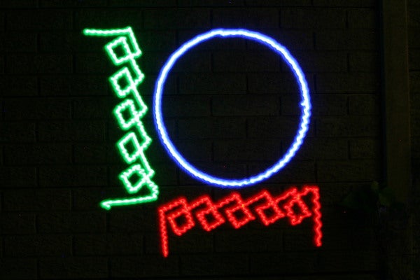
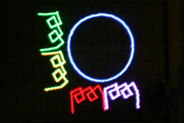
The repeatability of an automated light painter allows for some interesting options, such as animation:
System Overview
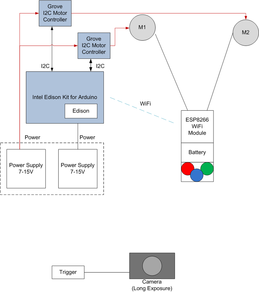
The RGB led is suspended from two strings, the other end of each is wrapped around a pulley on a stepper motor. By Shortening or Lengthening the strings, the LED can be positioned at any X,Y coordinate between the two motors.
The stepper motors themselves are each driven by a Grove I2C motor driver. The motor drivers receive commands from the Edison via the I2C protocol.
The colour of the RGB LED is controlled by an ESP8266 WiFi module, which receives commands from the Edison (or can be controlled manually by a laptop of cellphone). The LED and ESP8266 are powered by a battery, so they have the associated voltage regulation circuitry as well.
The software that handles the coordinate geometry as well as the stepper control, LED control and SVG importing is all written in the Python programming language and runs on the Edison itself.
Here you can see the "light pen" hanging in place, suspended from the two pulleys
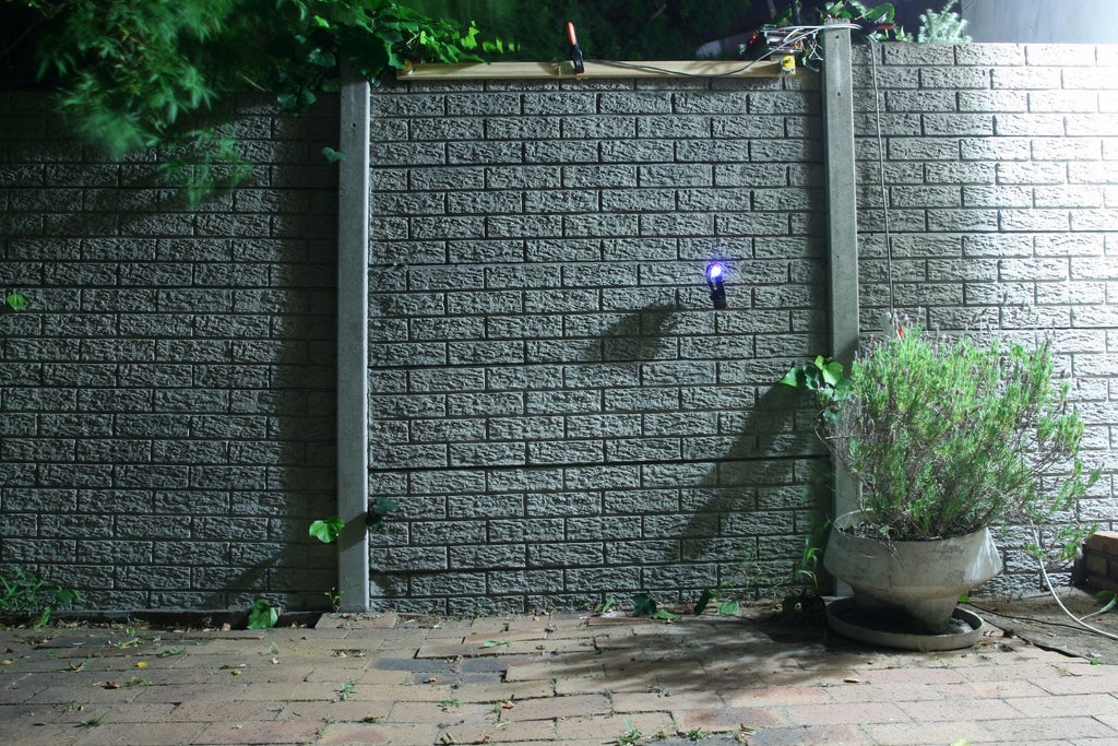
And here is the result of moving it around while the camera takes a long exposure photo.

Prior Art
String plotters are by no means a new idea, but this one is the first I have seen with wireless control of an RGB LED over WiFi and driven by Python.
This guy has made one that works on a XY gantry, but it's "art", so if that's your jam you can read my Instructable with some arty bollocks in mind.
And this chap has done one with string like me, but only in one colour,
Why you should read
Learn how to
- Use Python to control the Intel Edison
- Drive Stepper motors
- Upload New firmware to Grove I2C Motor Drivers
- Convert SVG to XY line segments
- Control an ESP8266 with an Intel Edison
Even if you have no desire to build a string plotter, I hope that you will find something useful in here. I have tried to describe each module in a useful way, so that the concepts can be applied to other things too. One last thing. if you like my project, please consider voting for me in the contest, thanks!
Step 1: Parts Used


Here is a list of all the parts that I used.
For the Mechanics
- 2x Stepper Motors (salvaged from printers: read motor section for details)
- Nylon Fishing Line
- Wood (or anything else to mount the motors to)
- 2x 3mm Prop Adaptors (to attach pulleys to 3mm motor shafts)
For the Controller
- 1x Intel Edison
- 1x Intel Edison Arduino Breakout Board
- 1x Grove Base Shield (or not, I made my own)
- 2x Grove I2C Motor Driver
- 2x Stepper Motors (salvaged from printers)
- 1x Wifi Antenna
- 1x Power Supply (I used a 5V/12V supply, but read the motor section first)
For the Wirelessly Controlled Light
- 1x ESP8266 Wifi Module
- 1x RGB LED
- 1x 3.3V Switchmode Regulator
- 1x 5V Switchmode Regulator
- 1x 3.3V FTDI Programmer
For the Camera
- Any camera with "bulb" setting
- Camera trigger (i made my own)
Sundries
- Resistors
- Wires
- Proto-board
- Solder
Step 2: Set Up Your Intel Edison

Getting Started
There is not much that I need to say about setting up the Edison, since it is covered admirably in these videos from Intel.
Software and Updates
This Instructable (link) is very helpful if you are new to running Python on the Edison.
Make sure that both Yocto (the linux distribution running on Edison) and MRAA (the libraries that provide easy access to the I/O ports) are up to date. This page has a good in-depth description on the procedure.
Setting up WiFi and SSH
Later in this Instructable I will discuss configuring the Edison as an access point, but for now make sure to log in via the terminal (using telnet) and run the "configure_edison --setup" command, then follow the prompts. It is important that you provide a device name and a password here, since they will be used as SSH credentials.
This process is described well here if you need help.
Transferring Files
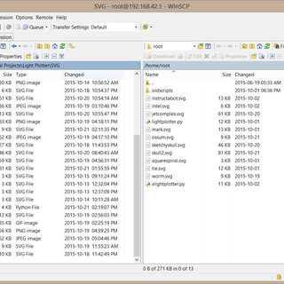
There are a few ways to transfer files to and from the Edison. my preferred option however is via the SCP protocol.
If you are using windows you can simply download WinSCP and access the Edison using the credentials that you set up during the WiFi configuration.
Useful Resources
These are some pages that I found very helpful while learning how to use the Edison
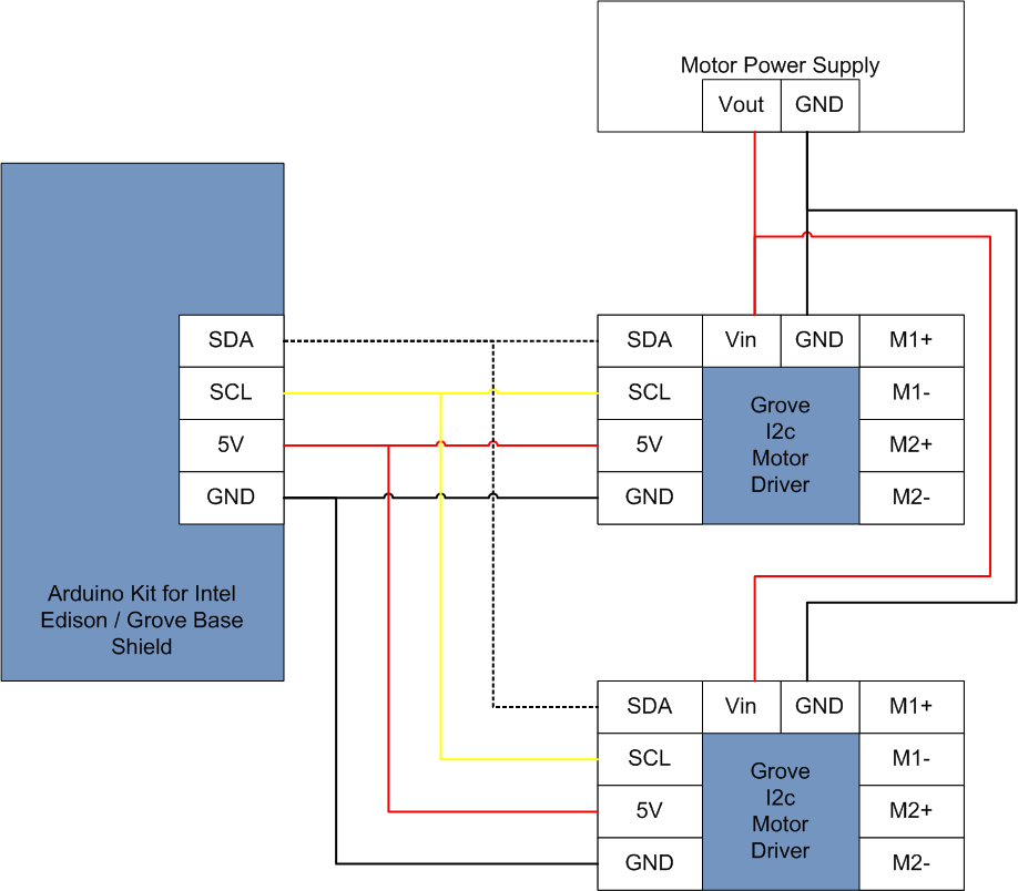
Step 3: Connect Motor Drivers, Supply Power


Wiring Overview
Power
The Edison kit comes with a wall-wart for power, there is no reason not to use it to power the edison, however, it cannot supply enough current to power the motors as well. You can read more in my motor section, but I ended up using a 5V 8A supply for my motors, you may choose something different.
Base Shield / Motor Control
Communication with the Grove Motor Drivers is via a protocol called I2C (here is a good tutorial if you are unfamiliar). A Grove Base Shield is the easiest way to connect up grove modules, since it plugs straight into the "shield" headers and provides a I2C socket with the same connector that all of the Grove modules use, but it is not neccessary.
All that you really need to do is connect the wires as per my diagram below. I made a simple equivalent to the Base Shield with some perfboard as you can see in my photos.
Remember to remove jumper J4 if you are powering the motor drivers externally like this. I kept the 5V connected so that I could reattach the jumper and run the motor boards without their supply (no motors connected) if I wanted to.
Power
I decided to build a power distribution board to make it easier to hook up the Edison, Motor Drivers and Fans. It is nothing more that a piece of perfboard with a collection of connectors soldered on to it.
The input voltage for the Edison Arduino Board is 7 - 15V, be careful not to exceed this. I popped the regulator onboard mine by accidentally connecting 18V.
The input voltage for the motor drivers is 6-15V. If you have one that can supply the current, then it would be possible to drive everything off the same supply (but read my motor section first, it explains why I made the choices that I did).
Step 4: Standalone Network, Edison As an Access Point

Configure the Edison as an access point
Presumably by this point you have configured you Edison as a wifi client by using the "configure_edison" tools and following the prompts.
configure_edison --setup
configure_edison --wifi
In order to change it to work as an access point, simply start the hostapd daemon
systemctl enable hostapd
Now when you scan for an access point you will see one with your Edison's name. The passphrase will be the same as your root password. All of the details are stored in "/etc/hostapd/hostapd.conf"
They can easily be found with
cat /etc/hostapd/hostapd.conf | grep ssid
cat /etc/hostapd/hostapd.conf | grep wpa_passphrase
DHCP
By default the Edison will have the address 192.168.42.1 and will give our IP addresses starting at 192.168.42.20
This is defined in "/etc/hostapd/udhcpd-for-hostapd.conf" as seen below
start 192.168.42.20 #default: 192.168.0.20<br>end 192.168.42.254 #default: 192.168.0.254</p>
Configure ESP8266 to connect to the Edison
Now modify the Edison's init.lua script to connect to your edison's access point, in my case it was
wifi.sta.config("lightplot","lightplot")At this point the Edison and the ESP8266 will be on their own standalone network and able to communicate.
Access from you computer
Connect to the "lightplot" access point with your phone of computer and you will see that you can SSH into the Edison on 192.168.42.1 or connect to the ESP8266's web page (assuming you have programmed it already) on 192.168.42.2
Step 5: Motors and Drivers (Test With Basic Python)


Types and Sources of Stepper Motors
If you are not familiar with stepper motors, I recommend reading some online introductions, this instructable and this Adafruit article is really nice and clear.
I salvaged my motors out of old printers and an electric typerwriter, scanners are also often a good source, laser printers are not.
Bipolar Stepper
If the motor has 4 wires then it is a bi-polar motor and we can use it. Measure the resistance between each of the four wires, you will find two pairs, these are the coils.
Unipolar
If the motor has 6 wires they represent the ends and middle of the two coils. Measure between all the combinations of the six wires, there will be 4 low resistance pairs (half coils) and two of twice that (full coils). We want to use the two full coils in series, so look for the two largest resistance pairs.
Connections
As noted in the previous step, if you are powering the motor boards externally, make sure to remove jumper J4 from the I2C driver board.
Connect the coils to the motors board, you can use the 4-pin header or the two screw terminals, they are directly connected to each other.
If you are using my code, one coil goes across M1+/M1- and the other goes across M2+/M2-. If you are using Grove drivers then, for some bizarre reason, one coil goes to M1+/M2+ and the other goes to M2+/M2-.
Current Voltage Limits
Reading the Grove Wiki or the datasheet of the L298N that I have attached tells us that the h-bridge chip has a current limit of 2A per channel and an input voltage range between 6-15V
The resistance of the coils determines how much current can flow through the motors.
Current = Voltage/Resistance
I initially tried some 60 ohm motors at 12V (0.2A), but they weren't producing enough torque. I then managed to find some 4.8 ohm motors, 12V would have drawn 2.5A which was too much continuous current, so I reduced the power supply on the motors to 5V resulting in a comfortable 1A draw with decent torque.
You also need to make sure that the power supply you use to power the motor boards can handle both motor's peak current simultaneously.
Cooling
The L298N chip can get pretty hot when operating near its current limits, so attaching a heat sink is a good idea. I had some fans salvaged from old electronics, so I used them to keeep the motor drivers cool.
Steppers with very low resistances (like the <10 ohm motors I used) are driven with current-limiting circuits (called "choppers"), so they will get pretty hot in this continuous current mode, but mine survived, your mileage may vary.
Set addresses of the motor drivers
Set the adresses on the motor drivers (they must be different). I set mine as per the descriptions in the wiki and chose '0x0a' and '0x0f'
More notes
- You should be able to run the command "i2cdetect -y -r 6" from the Edison terminal to see the connected I2C devices, but I encountered some bugs when I tried that that may or may not be fixed by the time you read this.
- Be sure that you have the latest MRAA libraries installed (i followed this guide)
- Only 100khz I2C is supported is supported by the Grove I2C Motor Drivers (this is not a problem for our project, it could be an issue when trying to use them along with other modules.
- The module does not provide any telemetry or status - it only accepts I2C commands for its various operations. This is why I didn't use the free-running stepper functions, since I wouldn't have know when they had finished the steps.
Useful Software Library Documents
Intel Page on Grove I2C Motor Driver (code examples, but not for steppers)
Test Software: Python Snippets
The easiest way to test these code snippets is:
- log in with SSH via putty
- enter the command "vi test.py" to create a new file called "test.py" and open it for editing with the texteditor "vi"
- press "i" to enter insert mode
- select and copy the code snippet on your PC
- right click into the SSH window to paste the code
- press escape
- type ":wq" to write and quit (or ":q!" to quit without saving changes)
- run the script with the command "python test.py"
Manual Stepping
This snippet of code is a bit of an ugly hack, but it works to test stepper motors from the Edison via Python. It simply steps through four steps, changing the polarity of the coils manually. It is not using the free-running stepper functions. This is how i ended up doing it in the end, but I increased the number of steps to eight (half stepping).
import time
import pyupm_grovemd as upmGrovemd

I2C_BUS = upmGrovemd.GROVEMD_I2C_BUS
I2C_ADDR = 0x0f

# Instantiate an I2C Grove Motor Driver on I2C bus 0
myMotorDriver = upmGrovemd.GroveMD(I2C_BUS, I2C_ADDR)
myMotorDriver.setMotorSpeeds(255, 255)
time.sleep(0.5)

steps = [[0,1],[2,0],[0,2],[1,0]]
nextStep = 0
steptime = 0.05

numSteps = 48

while True:
  for step in range(0,numSteps):
    myMotorDriver.setMotorDirections(steps[nextStep][0],steps[nextStep][1])
    nextStep += 1
    if nextStep > 3:
      nextStep = 0
    time.sleep(steptime)
Free Running Stepper
This is an example of how to use the free running stepper functions. There are some things to watch out for
- The coils are not connected "on on M1 one on M2" as one might expect.
- The speed arg is "backwards", it is more like a delay between steps (and 0 is still not very fast)
- The stepper does run in the background as promised, but when the python script stops, something interrupts it (hence my "Press any key to continue...").
import time
import pyupm_grovemd as upmGrovemd

I2C_BUS = 0
I2C_ADDR = 0x0f

# Instantiate an I2C Grove Motor Driver on I2C bus 0
myMotorDriver = upmGrovemd.GroveMD(I2C_BUS, I2C_ADDR)

#start up as a stepper motor
print "stepper clockwise"
myMotorDriver.setStepperSteps(48*4)

#time.sleep(1)
myMotorDriver.enableStepper(0,0) #direction 0 , speed 2
#time.sleep(20)

#myMotorDriver.enableStepper(1,2) #direction 0 , speed 2
#time.sleep(20)


#print "Stopping motors"
#myMotorDriver.enableStepper(upmGrovemd.GroveMD.STEP_DIR_CCW,0)

#myMotorDriver.disableStepper()
raw_input("Press any key to continue...")
Attachments

Step 6: Upgrade I2C Motor Drivers Firmware

Note
In the end I did not use these features, so you can skip this step unless you required them. I include it here because the documentation on the web is not at all easy to find.
My motor drivers responded to the motor control modes, but not the continuous stepper functions, so I used my Arduino Nano to flash the latest v1.3 firmware onto the ATMEGA8 on the motor driver board. This document was particularly helpful (attached here, in case it disappears).
This step is only necessary if you wish to use the "continuous running" stepper function of the driver boards which have only been available since v1.3. Despite my boards being marked V1.3, they in fact only had firmware 1.2 loaded.
Download the latest firmware
Go to the Grove Wiki and find the firmware under resources at the bottom of the page (it is a .zip file containing a .hex file)
Procedure
These were the commands I ran on my PC to flash the firmware via my Arduino Nano.
avrdude -P COM17 -b 19200 -c avrisp -p atmega8 -n
avrdude -P COM17 -b 19200 -c avrisp -p atmega8 -u -U flash:w:"C:\mega8motor.hex":i
Note, I was lazy and put mega8motor.hex in C root to make that directory clearer
Attachments
Step 7: Understanding the Geometry of a String Plotter ('V' Plotter)

Before we can get started with the code, it is important to understand how the motors can move the LED to exactly the X,Y point in space that we want. Fortunately, for a change, the maths is incredibly simple.
If we can work out the length of S1 and S2, the two strings, and we know how long S1 and S2 currently are, then all we have to do is take (Sgoal -Scurrent)
I measure the string length in "steps", its real world length is completely irrelevant.
- S1 and S2 are the lengths of the strings that we want to figure out
- (X,Y) is the point we want to go to
- Rx is the distance between the two pulleys
- (0,0) is the origin (the top left pulley)
We have a position (X,Y) that we want to go to.
Pythagorus says:
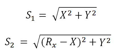
And that is it!
There are some assumptions being made here:
- The string doesn't stretch (it does)
- The motors have no torque limit (they do)
- There is sufficient tension on the strings at all coordinates (there isn't)
The end result of these assumptions is that we cannot move (x,y) too close to the edges (directly below the motors, because one string will get loose) or to close to the 'top' (directly between the motors) because the tension will be too much and cause the motors to skip steps. This is all easily avoided and will be handled in the software.
Step 8: NodeMCU on the ESP8266

Why the ESP8266?
I wanted to be able to control the colour of the RGB led (our "light pen") via WiFi, so I used one of the ESP8266 modules with breakout boards that you can get for just a few dollars from Ebay or Aliexpress. I chose the ESP8266-07 module, since it had extra GPIO pins.
What does it need NodeMCU?
The ESP8266 is intended as a simple (and cheap) wifi to serial bridge, which is pretty cool in itself, but some smart people have figured out that we can also reprogram the onboard microcontroller and get it to run our own code, which is exactly what we are going to do.
There are a few options, but for the dead-simple use case that I am going for, I thought I would stick with the well documented "NodeMCU" firmware.
I recommend that you follow these two tutorials, since they describe the process very clearly.
In particular, I started with the ultra basic web server, and modified it for my own needs. I reckon its easier to make the Python on the Intel Edison pretend to be a web browser than get low-level comms working between the two. This also provides the distinct advantage that the LED can be controlled easily from a laptop or phone if needed for debugging.
Important Note: The ESP8266 runs off 3.3V, not the 5V you may be accustomed to with Arduino (or the Intel Edison Arduino Breakout Board). Supplying you ESP with 5V will fry it, and even giving it a 5V logic input is likely to damage it.
Since I was planning to run my ESP and the LEDS of batteries, I chose a 3.3V switchmode regulator with a wide input range (9-25V) that I had lying about (PT78ST133S). If you just want to use a single cell battery, you could probably get away with a linear regulator.
Some gotchas when flashing
There were one or two things that I had to do that I didn't see written anywhere
- Reboot the ESP8266 once the flash tool was opened
- Set the baud rate to 115200 (but this may not be the case for all of them)
Check that the flashing has worked by logging in with putty over the serial connection (9600 baud now)
Step 9: Build ESP8266 Circuit

Power Supply
The ESP8266 is a 3.3V chip (unlike the 5V logic that many folk are used to), so the supply voltage must be regulated.
3.3V is a touch too low to drive the blue LED via a transistor (there is a 3.2V drop across the LED and a 0.7V drop across the transitor), so I used a 5V regulator to power the LED circuit.
These are the exact parts I used, but that was only because I had them lying about, you can use whatever is cheap and convenient.
- 3.3v supply (9 - 26V input) (digikey)
- 5.5v supply for LEDs (7 - 28V input) (digikey)
I used a 2s (7.4V) LiPo battery to power the circuit, since I have them from my RC car. The 2800mAh battery that I used will run the circuit for many hours.
Switching LEDS
The ESP8266 GPIO pins cannot source/sink enough current to drive the LEDs at full brightness (especially if we want multiple LEDs per colour), so we build a simple transistor switching circuit where the GPIO pin turns on a transistor and the transistor allows current through the LED.
The current through the LEDs must be limited. Check out the datasheets of the ones you buy, but 20mA is generally a good limit for bog-standard 5mm LEDs.
Next, we determine the voltage drop across each LED (check the datasheet or measure with your multimeter).
Mine were:
- Red: 2V
- Green: 3.2V
- Blue: 3.2V
Current = Voltage/Resistance
so for 20mA each I needed the following resistors
- Red: (5.5-0.7-2)/(0.02) = 140 Ohms
- Green: (5.5-0.7--3.2)/(0.02) = 80 ohms
- Blue: (5.5-0.7-3.2)/(0.02) = 80 ohms
If you are unclear on this process, there are many tutorials on the web, or even right here on instructables
Discrete LEDS vs RGB common-anode/common cathode
You can use discrete LEDS as in my circuit, or you can get combination RGB leds which come in two varieties:
- Common Anode (positive side of the three LEDS are tied together)
- Common Cathode (negative side of the three LEDS are tied together)
The circuit in my diagram can be used as-is with a common-cathode RGB LED, but would require modification to "low side switching" if one wanted to use common-anode LEDs.
Wiring up the ESP8266
You will already know how to wire up the EP8266 from the previous step, and can check back in at this tutorial if it isn't clear.
Step 10: Program the ESP8266 to Control RGB Leds

Now that we have NodeMCU installed on the ESP8266 and a circuit to control the 3 colour LEDS, it is time to write some LUA software to allow us to control the LEDs over WiFi.
I decided that the easiest way would be to implement a web server on teh ESP8266 with 3 sliders, one for each colour's brightness.
This method has some pros and cons
Pros
- Quick and Easy, there are plenty of tutorials on setting up basic web servers as well as how to to handle PWM.
- The LED colours can be controlled programatically via Python on the Edison, or via the webpage (on your PC or Phone). This is great for debugging.
Cons
- Slow. Setting the colour via HTTP takes a noticeable fraction of a second. I decided that this wasn't an issue for me.
GPIO Indexes
You need to know which pins are which and this NodeMCU GPIO index will tell you: link
PWM
This page has a a basic PWM function example: link
Web Server
This page describes how to set up a web server on the ESP8266: link
Configure As a Station
The ESP8266 is usually configured as an access point by default, but I wanted mine to connect to my Edison which is the Access Point, so I use the "wifi.setmode"
Sliders
The sliders are standard HTML "range" elements, configured to have values from 0-1023, which is what the PWM function expects.
Storing Values
You will see that I included variables "currentR", "currentG" and "currentB" that store the last configured LED value, so that the webpage can display it correctly after refreshing.
ledR = 5 --GPIO14
ledG = 7 --
ledB = 6

function led(r,g,b)
    pwm.setduty(ledR,r)
    pwm.setduty(ledG,g)
    pwm.setduty(ledB,b)
end

wifi.setmode(wifi.STATION)
wifi.sta.config("lightplot","lightplot")

wifi.sta.setip({ip="192.168.42.2",netmask="255.255.255.0",gateway="192.168.42.1"})


gpio.mode(ledR, gpio.OUTPUT)
gpio.mode(ledG, gpio.OUTPUT)
gpio.mode(ledB, gpio.OUTPUT)

pwm.setup(ledR,500,0)
pwm.setup(ledG,500,0)
pwm.setup(ledB,500,0)

pwm.start(ledR)
pwm.start(ledG)
pwm.start(ledB)

currentR = 0
currentG = 0
currentB = 0

led(currentR,currentG,currentB) -- red

srv=net.createServer(net.TCP)
srv:listen(80,function(conn)
    conn:on("receive", function(client,request)
        local buf = "";
        local _, _, method, path, vars = string.find(request, "([A-Z]+) (.+)?(.+) HTTP");
        if(method == nil)then
            _, _, method, path = string.find(request, "([A-Z]+) (.+) HTTP");
        end
        local _GET = {}
        if (vars ~= nil)then
            for k, v in string.gmatch(vars, "(%w+)=(%w+)&*") do
                _GET[k] = v
                if (k == "RED")then
                  currentR = v
                end
                if (k == "GREEN")then
                  currentG = v
                end
                if (k == "BLUE")then
                  currentB = v
                end

            end
        end

        led(currentR,currentG,currentB);

        buf = buf.."<html>";
        buf = buf.."<h1> ESP8266 Web Server RGB LED</h1>";
        buf = buf.."<form  method=\"get\">";
        buf = buf.."<p> RED <input type=\"range\" name=\"RED\" min=\"0\" max=\"1023\" value=\""..currentR.."\"> </p>";
        buf = buf.."<p> GREEN <input type=\"range\" name=\"GREEN\" min=\"0\" max=\"1023\" value=\""..currentG.."\"> </p>";
        buf = buf.."<p> BLUE <input type=\"range\" name=\"BLUE\" min=\"0\" max=\"1023\" value=\""..currentB.."\"> </p>";
        buf = buf.."<p> <input type=\"submit\"> </p>";
        buf = buf.."</form>";
        buf = buf.."</html>";

        client:send(buf);
        client:close();
        collectgarbage();
    end)
end)

Step 11: Program Comms Between ESP8266 and Edison Over Wifi

If you connect to the webpage served up by the ESP8266, as we configured it in the last step, you will see it shows three sliders, one for each colour LED.
Once you set the sliders to a value and press the button you will see that the URL in your browser contains values for the 3 sliders.
Mine looks like this when I set the colour (169,123,119), my ESP8266 has been configured with the address 192.168.42.2 which is in the same subnet as the Edison's default 192.168.42.1
<a href="http://192.168.42.20/?RED=169&GREEN=123&BLUE=119">http://192.168.42.2/?RED=169&GREEN=123&BLUE=119</a>
It is easy to emulate this from a Python script, we basically get the Edison to pretend that it is a web browser requesting a page.
The following Python snippet would cause the Edison to set the colour (169,123,119) just like we did from the browser.
import urllib2
urllib2.urlopen('http://192.168.42.2/?RED=169&GREEN=123&BLUE=119')
Step 12: XY Coordinates From an SVG (Python Code)


Intro
We need an easy way of creating the pictures that we want to draw, so I chose to use Inkscape (which is free) to draw SVGs (scalable vector graphics). An SVG is actually an XML based file type, so you can parse it easily enough with python. It can get very complicated , but if we limit our drawings to path objects, it is simple.
The python code I have written below can be run on your computer so that you can view the output, once you understand it it is easy to implement the same thing on the Edison in our controller.
Drawing
First intall inkscape, and draw something simple with the line tool (my drawing of the Intel logo is attached)
Make sure that coordinates are set to absolute by following these steps:
- shift+control+p
- input/ouput
- svg output
- path data
- path string format: absolute
If you draw complicated paths or use the tracing tools, make sure to first "break apart" the paths, or the script won't handle them.
Once you have applied that setting, select the whole image (ctrl+a) and move it to refresh the coordinates, then save as an svg
Using absolute coordinates dramatically reduces the processing that we need to do to turn out SVG paths into line segments defined by pairs of x,y coordinates.
Python Code
Here is a tiny bit of python code that reads in an SVG file and, using the "minidom" module, parses the file for paths.
Each path consists of a series of commands (such as 'M' or 'L') followed by a coordinate. Here are some examples (read this for the nitty-gritty: link):
- 'M' means, "move the pen to this coordinate"
- 'm' means, "move the pen this far, relative to current position"
- 'L' means, "move the pen to this coordinate, while drawing a line"
- 'm' means, "move the pen this far, relative to current position, while drawing a line"
- 'Z' or 'z' means. "draw a line back to where we started (close the shape)
I chose just to deal with "M', "L" and "Z" in this example, hence the requirement for absolute coordinates.
I have also included a little code which uses Matplotlib (a python plotting tool) to draw the SVG and save it as a PNG for viewing.
from xml.dom import minidom
import re

class svgHandler:

  def __init__(self):
    self.filename = ""
    self.lines = [] #list of segments of the form [x0 y0 x1 y1 RGB] where x and y are 0-1 floats

  def importFile(self,filename):
    doc = minidom.parse(filename)  # parseString also exists
    paths = doc.getElementsByTagName('path')
    doc.unlink()
    pathsandcolours = []
    self.lines = []

    """
    Go through the paths and store their coordinate strings and colours in a list of tuples
    """
    for p in paths:
      styleValues =  p.attributes['style'].value.split(";")
      for val in styleValues:
        if val.split(":")[0] == 'stroke':
          rgb = val.split(":")[1]
      pathsandcolours.append((p.getAttribute('d'),rgb))

    """
    For each path and its corresponding colour, convert to a set of line segments of the form [x0 y0 x1 y1 RGB]
    """
    xMin = float("inf")
    xMax = -float("inf")
    yMin = float("inf")
    yMax = -float("inf")
    unScaledLines = []

    for path,rgb in pathsandcolours:
      pathCoords = re.split(r'([CcLlMmZz])',path)
      startX = 0
      startY = 0
      lastX = 0
      lastY = 0
      newLine = True
      closeLine = False
      #we are assuming absolute coordinates in the SVG

      print pathCoords
      for coord in pathCoords:
        coord = coord.strip()
        if len(coord) == 0:
          pass
        elif coord == 'M': #'M' is move cursor to absolute position
          newLine = True
        elif coord == 'L': #'L' is draw line to absolute position
          newLine = False
        elif coord == 'Z' or coord.strip() == 'z': #close line to initial point
          closeLine = True
        else:
          try:


            x = float(re.split(r'[\s,]',coord)[0])
            y = float(re.split(r'[\s,]',coord)[1])
            xMin = min(xMin,x)
            yMin = min(yMin,y)
            xMax = max(xMax,x)
            yMax = max(yMax,y)

            if closeLine:
              lastX = x
              lastY = y
              startX = x
              startY = y
              unScaledLines.append([lastX,lastY,startX,startY,rgb])
            elif newLine:
              lastX = x
              lastY = y
              startX = x
              startY = y
            else:
              unScaledLines.append([lastX,lastY,x,y,rgb])
              #self.lines.append([lastX,lastY,x,y,rgb])
              lastX = x
              lastY = y
          except:
            print "unhandled command: ",coord

      #print "xMin,yMin",xMin,yMin
      #print "xMax,yMax",xMax,yMax

    xTotal = xMax-xMin
    yTotal = yMax-yMin


    for x0,y0,x1,y1,rgb in unScaledLines:
      X0normalised = (x0-xMin)/xTotal
      X1normalised = (x1-xMin)/xTotal
      Y0normalised = (y0-yMin)/yTotal
      Y1normalised = (y1-yMin)/yTotal
      self.lines.append([X0normalised,Y0normalised,X1normalised,Y1normalised,rgb])

  def plotPath(self):
    import matplotlib.pyplot as plt
    plt.gca().invert_yaxis()
    for x0,y0,x1,y1,rgb in self.lines:
      print int(rgb[1:3],16),int(rgb[3:5],16),int(rgb[5:7],16)
      plt.plot([x0,x1],[y0,y1],color=rgb)
    plt.savefig(self.filename.split('.')[0]+'.png')
    plt.show()


svgh = svgHandler()
svgh.importFile("example.svg")
svgh.plotPath()
Attachments
Step 13: Python Code to Drive the Steppers

Why do this in Python?
It is possible to send the Grove I2C Motor Driver V1.3 a command to run a stepper for a specified number of steps without having to specify each step individually, but this doesn't help us, we need to know exactly when each step is happening and when a series of steps are complete, so that we can turn the LED on and off at the right time.
If you want the free-running stepper features of this board and you're motor driver is only loaded with V1.2 like mine was, then you will need to upgrade the firmware like I did earlier in this Instructable.
Also, I just like Python.
But Python isn't realtime, you can't drive motors with it!
That is true, and that isn't true. It's close enough to realtime for this purpose. If the step times are slightly inconsistent it really is not a big deal. I did however take care to run processes in threads, so that the motors can run simultaneously, and other processes (such as turning the LED on and off) are handled in threads so that they don't disturb the stepping time and hence the momentum of the LED assembly (which would cause oscillations).
The Stepper Class
In Python I created a stepper class which stores a few variables about the motors current state
- steps: This array contains the 8 individual polarity pairs that make up a full rotation for a half-stepping motor
- nextStep: This is the index of the next step in the array to be used
- direction: We store the direction that will lengthen the string, this basically determines whether we are stepping forwards or backwards through the array.
class stepper:
  steps = [[2,2],[2,0],[2,1],[0,1],[1,1],[1,0],[1,2],[0,2]]
  nextStep = 0
  direction = 1 #1 or -1 #can be inverted to invert motor direction
  stepCount = 0
The stepper motor's initialisation function sets up the GroveMD drivers. Make sure to use the correct I2C address as configured on the board's dip switches.
Take note of "setMotorSpeeds" , which sets the PWM of the motor driver. For steppers the PWM should always be 255 when active or 0 when disabled, it does not affect speed, the delay between steps sets that.
  def __init__(self, I2C_ADDR, I2C_BUS,direction):
    self.motorDriver = upmGrovemd.GroveMD(I2C_BUS, I2C_ADDR)
    self.motorDriver.setMotorSpeeds(255,255)
    time.sleep(0.05)
    self.direction=direction
The step() function takes in one argument which is either True or False. If the argument is True then the motor steps in the direction that will lengthen the string.
  def step(self,lengthen):
    """
    Take one step in either direction.
    Takes a boolean argument to indicate lengthen or shortening string
    """
    if (lengthen):
      self.stepCount += 1
      self.nextStep += self.direction
    else:
      self.stepCount -= 1
      self.nextStep -= self.direction

    if self.nextStep > 7:
      self.nextStep = 0
    if self.nextStep < 0:
      self.nextStep = 7
    self.motorDriver.setMotorDirections(self.steps[self.nextStep][0],self.steps[self.nextStep][1]
Step 14: Bring All the Code Together

This is an overview of the code that has been discussed in the previous steps. My final file is attached for your use.
The code consists of these classes
- lightPen
- SVGHandler
- stepper
- lightPlotter
- cmdInterface
LightPen Class
This class handles communication with the ESP8266 wifi-controlled RGB LED via an HTML interface. It has three functions
setColourRGBTuple() This function is used to set the current colour to an RGB value provided in the form of a tuple (R,G,B), where the values R,G and B are between 0 and 255 (base 10 - decimal)
setColourHexString() This function is used to set the current colour to an RGB value provided in the form of a hex string '#rrggbb', where the values rr,gg and bb are between 00 and ff (base 16 - hex)
setColour() This function is called by setColourRGBTuple or setColourHexString to apply the colour to the LEDS via HTML request. If we called this function directly in between motor steps it could cause a delay and interfere with the smoothness of our stepping. In order to avoid this it is called in a thread, so that it runs simultaneously with the stepping code.
SVGHandler Class
This class' operation was explained in the step "XY Coordinates from an SVG" In short it reads in an SVG (that is assumed to have absolute coordinates only and straight-line path objects only) and stores them as a list of beginning and end coordinates of lines, along with the line's colour. The segments form a list of lists, with each segment having the form [x0 y0 x1 y1 RGB]. the x and y coordinates are normalised floats (scaled so that the minimum is 0 and the maximum is 1).
Stepper Class
This class is described in the step "Python Code to drive the steppers". It handles the I2C communication with the stepper motors and provides a simple step() function which either moves the stepper forwards or backwards one step.
LightPlotter Class
The LightPlotter class brings all of these other classes together into a system that can draw pictures with light. During initialisation there are a few key variables that are configured
- the two motors are defined as motor1 (left-hand motor) and motor2 (right-hand motor), these are instances of the stepper class
- The number of horizontal steps between motor1 and motor2 are defined (xRes). This needs to be determined experimentally and will depend on the diameter of your pulleys and the distance between the motors.
- The defaults time between steps (stepTime) is defined. a value of 10mS (0.01) worked well for me, but you will have to determine how fast you can step without missing steps.
- The maximum step time (stepTimeMax) is also defined, but this is really just a safety for certain calculations, it does not have a hardware relevance, I chose 1 second, which was never reached in practice.
- usableArea. As described in the the "Understanding the Geometry of a String Plotter" step, the extremities directly under the motors and directly between the motors (at the top) should be avoided, so I define a variable "usableArea" which is a percentage of the theoretical area. 70% (or 0.7) is a good starting point.
- Sometimes you may want to shift your entire image down (for example, to draw a character's feet on the floor), the "yOffset" variable takes care of this
These are the lightPlotter class' functions
- setOrigin
- goTo
- runSteppers
- stepMotors
setOrigin() is used to tell the light plotter that it is currently at (0,0) which is used in calibration.
runSteppers() is a convenience function that takes in a number of steps that each motor should turn, as well as the interval between steps for each motor. Using threads the two motors are both able to be stepped simultaneously.
goTo() takes in an (X,Y) coordinate and calculates the number of steps that each motor needs to move in order to get the LED to that location. In addition it determines the delay between steps to ensure that both motors take the same time to get to their destination. Once these details are calculated, goTo() makes use of the runSteppers() function to get the motors moving.
cmdInterface Class
This class makes use of the very cool Python module "cmd" allowing us to easily build a command line interface for our light plotter.
Functions that are prefixed with "do_" can be called from the command line when the script is run. You can see that they all correspond almost directly to the functions of the various classes, in most cases they include a bit of error checking to make sure that the arguments are sane. The "How to Use the System" step will describe how to use these.
- do_plotsvg
- do_movesteps
- do_invertMotor
- do_disableMotor
- do_enableMotor
- do_setrgb
- do_goxy
- do_goxyrgb
- do_setusable
- do_setorigin
- do_setyoffset
- do_exit
Attachments
Step 15: How to Use the System

Start The Program
Connect your PC to the Edison's WiFi and log in via SSH. Navigate to the directory where you saved your python script and run the script with the following command
python lightplotter.py
If you get an I2C error, press the reset buttons on the motor drivers and then try again
Calibration - Set Zero Point
Before the plotter can draw anything, it needs to know where its pen is. We achieve this by turning the motors until the LED is dangling in the top right corner, at the origin (0,0)
Due to the weight of my battery the motors usually unspooled after they have been turned off, so I would start a calibration by retracting both motors until the led is dangling in the middle between them, a few iterations of the following code will do (once you know how far to retract, you can do it quickly, but it is wise to be sure before telling the device to retract 2000 steps and you end up winding the led assembly right into the pulleys.
movesteps -300 -300
Once the motor at the top (y = 0) it needs to be moved to the left, so one repeats the following instruction a few times
movesteps -100 -100
When the led is finally at the origin, issue the command to zero the system
setorigin
Calibration - Set Usable Area
Since the plotter doesn't work particularly well at the edges, we set a restricted area to work in. I generally start with 70%
setusable 0.7
To check that the area is what I want, I move the LED to the extremities
goxy 0 0
goxy 1 1
Calibration - Set Y Offset
If you are drawing a picture that needs to touch the ground, you can set an offset to lower it.
setyoffset 0.2
then test the lowest point with
goxy 0 1
Camera Setup
At this point you need to make sure that your camera is set up.
- Connect the remote trigger
- Set to Manual Mode
- set aperture to f8.0 as a starting point (you can increase the number if there is too much ambient light)
- Set shutter to "bulb" (or the longest exposure if your camera cannot do bulb mode)
- Make sure that it is focused. This can be hard in the dark, so I use my cellphon to log in to the ESP8266's webpage and turn the LED on.
- Flip the switch on your trigger to start taking a photo.
Start Plotter
Tell the plotter to start plotting your sweet SVG with light
plotsvg mysweetsvg.svg
and now you wait (or in my case, spend the time fending off the cats that want to play with a jiggling-light-on-a-string) . Most of my examples in this Instructable took less than 5 minutes to plot, but the most complex one, attached to this step, took 20 minutes (and it's rubbish!).
That's it folks, thanks for reading! If you like what I did or appreciate the work I put in, please consider voting for me in the Intel IOT contest! Much appreciated :-)
Step 16: Room for Improvement
I have some ideas that could be useful if one wanted to use the system a lot, I leave them as an exercise to the reader since I expect I will be pulling the project apart to use the Edison in a robot or something ;-)
- Add and LCD and some buttons, and use them to control plotting SVGs from an SD card, then the whole system could be used outdoors without a computer.
- Add a web interface that can control printing (from and SD card or main memory), then the system can be controlled with nothing but a wifi-enabled cellphone/tablet
- Power the Edison and motor drivers from a battery. This is easy, just get a battery such as a 3S LiPo for RC cars, I would have done it if my only battery wasn't powering the light-pen.
- Add some limit switches so that calibration can be at least semi-automated. My first idea would be to hang small magnets on the string near the light-pen and use hall-sensors near the motors to detect them.

Second Prize in the
Intel® IoT Invitational

Participated in the
Make It Glow! Contest


