

Introduction: Light Seeking and Obstacle Avoiding Robot


The purpose of this project is to build an arduino robot that follows light and avoids possible obstacles in its way. It is based on an Arduino Uno microcontroller board and it uses Light Dependent Resistors to find the most bright light source while avoiding any obstacle on its way to the light source, using an Ultrasonic Distance Sensor.
The fun thing is that it has an old android smartphone on it and it broadcasts live onboard video to your computer screen. You can see what it can see.
Step 1: List of Components and Tools


Components
- Arduino Uno board
- Breadboard
- 2 x Continuous Rotation Servo
- 1 x Micro generic Servo
- Ultrasonic Distance Sensor (HC-SR04 is cheap and reliable)
- 2 x Light Dependent Resistors
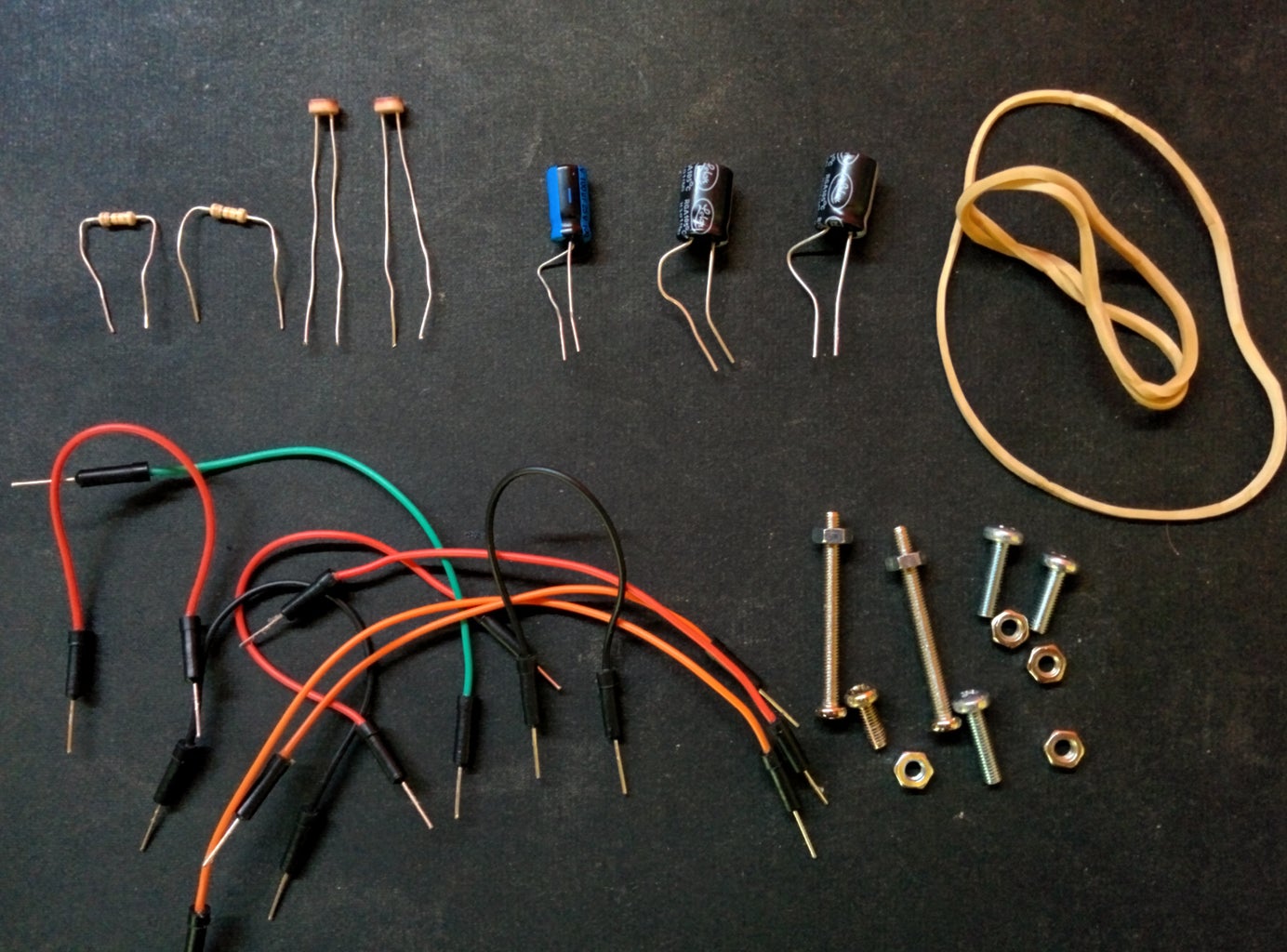
- 2 x 10kΩ resistors
- 2 x 330μF capacitors
- 1 x 100μF capacitor
- Robot Chassis (i used the magician chassis, you can use whatever you like, even cardboard)
- 2 x plastic wheels
- 9V battery for the servos
- 4 x 1,5V batteries for the Arduino
- Holders for the batteries
- Hook up wires
- Rubber bands
- Screws
- Zip ties
- Several supports for the components
- On/Off Switches (optional)
- Old Android Smartphone (optional)
Tools
- Screwdriver
- Wire cutter
- Duct tape (or electrical tape)
- Soldering iron (optional)
- Solder wick (optional)
Step 2: Assembling the Chassis and Motors


The first step is to assembly our chassis and put on the continuous rotation servos. You can use any chassis you want, it may be acrylic, aluminum or even from a cd case. I chose the Magician chassis (you can find it on ebay) because it has so much holes and so it can be very versatile for many projects.
So, first of all, screw the four plastic holders for the servos in the chassis. Make sure to tighten them up properly so they will not move. Next, attach the servo motors and screw the plastic wheels on them. Our wheels are ready!! You can use a rubber band to keep them straight because they may move left or right from the weight of the robot when we finish it.
Next, put the 4 batteries (1.5V each one) in the holder and attach it to the chassis using a rubber band. This is the power for the Arduino.
Step 3: Ultrasonic Sensor


It is time for the distance sensor. In this project i used an ultrasonic distance sensor, the HC-SR04, which is cheap and very reliable. Ultrasonic sensors work like this; they produce an ultrasonic sound which bounce on objects and then they receive it back. The amount of time that the sound needs to go from the sensor to the object and then back to the sensor gives us the distance in cm (or any other unit). We will talk about this in the programming section so don't worry.
What we want is to attach the distance sensor on the micro servo so our robot can check right and left when it encounters an object and choose the clear path to move on. I used a rubber band (what else) to support my sensor and screwed it in a metallic frame i found in my tool box. That way i managed to put it on top of the micro servo so it can move. You can put it directly in the servo with a piece of string to hold it in place, use your imagination and be creative!! This is a unique robot made from you!!
Step 4: Putting It Together


Now it is time to assemble the upper deck of the Magician chassis. Just screw it in place and put the arduino board on it. Next put the 9V battery holder in front of the arduino and the breadboard on top of it. I used blu-tack to "glue" them togoether so they will not move around. Again, you can use whatever you want to "glue" them. After that, put the micro servo with the distance sensor in the front side of the chassis and use use blu-tack to make it stand there. I used a zip tie to make sure it will not fall. Make sure to leave a gap between the breadboard and the servo-sensor "tower" so the sensor can move freely in both directions (left-right). I left a fairly big gap there and i slided my old smartphone between them so i can use the camera. I secured it using a single zip tie. That way it is safe and you can put it there or take it in your hand really fast. In order to have live video from your robot to your computer screen, all you have to do is to install the "IP Webcam" app to your smartphone and follow the instructions to do it.
You can also put an on/off switch in order to power your robot but this is an optional step. If you want to do it, simply cut the power wire from the batteries and solder it in the switch. Do not cut the ground wire.
Step 5: Light Dependent Resistors and Final Wiring


Light Dependent Resistors or just photoresistors, are the eyes of your robot. They are responsible for light detection and they will tell to your robot to move to the brightest light source. Place them to your breadboard, one on each side to determine the left - right orientation, and connect one end of the photoresistor to the power and the other to the ground through a 10kΩ (kilohm) resistor. Connect the left photoresistor to Analog Pin A2 on the Arduino. The right photoresitor goes to Analog Pin A0. If your robot goes to the darkest side of the room instead of the brightest just switch the pins and it will be ok.
Lets move on to the servos. Attach the 3 pin header of each of the servos in the breadboard. The colors of the wires indicate the purpose of each wire. Red is for the power, black goes to the ground and white goes to Arduino. Be careful not to mess with power and ground, or else you can damage the servo. Read carefully the instruction manual of your servo and write down what the color of each wire means. When a servo motor starts to move, it draws more current than if it were already in motion. This will cause a dip in the voltage on your board. By placing a capacitor accross power and ground right next to the male headers you can smooth out any voltage changes that may occur. For the two continuous rotation servos i used 2 x 330μF capacitors and for the micro servo i used 1 x 100μF capacitor. Be very careful to make sure you are connecting the cathode to ground (that's the side with a black stripe down on the side) and the anode to power. If you put the capacitors in backwards, they can explode. Now attach the left servo to Digital Pin 10 on the Arduino and the right servo to Digital Pin 11. Also, attach the micro servo to Digital Pin 6.
Finally, we must connect the distance sensor. Attach the Vcc pin to power, the Gnd pin to ground, the Trig pin to Digital Pin 7 and the Echo pin to Digital Pin 4 on your Arduino. Thats it!
Lastly, we must connect power to our breadboard. As you can see in the image that shows the schematic of our circuit, i have used two different power sources in the same breadboard. One is for the servos and the other for the sensors. Be very careful not to mix the wiring because you will be in trouble. Follow the schematic picture and pay attention!
We just built our robot!!!
But it cant do anything until we programme it. So lets go!!
Step 6: Arduino Code
First of all you need to center your continuous rotation servos. By centering them, i mean to stop them from spinning freely all the time. Type the code below and upload it to your arduino. Now two things are going to happen. Either the servos will not spin, which means that they are already centered, or they will spin at some speed. If they spin you must do something. Continuous servos have a screw in the side where their cables are. Take the screwdriver and while the servo is spinning screw or unscrew the screw a little bit until the servo stops. This is how you center them. The brake (center) is at 90, full throttle left is 0 and full throttle right is 180.
#include
Servo leftMotor;
Servo rightMotor;
void setup() {
rightMotor.attach(11);
leftMotor.attach(10);
}
void loop() {
rightMotor.write(90);
leftMotor.write(90);
}
Now you are ready to programme your arduino robot!! Get that code and upload it to your Arrduino!! Hopefully everything is going to work perfectly!!
#include //include Servo library
#define trigPin 7 //the trig pin from distance sensor
#define echoPin 4 //the echo pin from distance sensor
const int RForward = 120; //the speed of the servo, maximum speed is 180
const int RBackward = 60;
const int LForward = 60;
const int LBackward = 120;
const int RNeutral = 90; //centered position
const int LNeutral = 90;
const int RightLightSensor = 0; //declare the analog pins for the photoresistors
const int LeftLightSensor = 2;
const int collisionThresh = 15; //threshold for obstacles (in cm)
int SensorLeft;
int SensorRight;
int SensorDifference;
int leftDistance, rightDistance; //distances on either side
Servo panMotor; //micro servo with the distance sensor on it
Servo leftMotor; //declare motors
Servo rightMotor;
long duration; //time it takes to recieve PING))) signal
void setup() {
rightMotor.attach(11); //attach motors to proper pins
leftMotor.attach(10);
panMotor.attach(6);
panMotor.write(90); //center the pan servo
pinMode(trigPin, OUTPUT);
pinMode(echoPin, INPUT);
pinMode(LeftLightSensor, INPUT);
pinMode(RightLightSensor, INPUT);
}
void loop(){
int distance = ping(); //call the ping function to get the distance in front of the robot
SensorLeft = 1023 - analogRead(LeftLightSensor); //read the photoresistors
delay(1);
SensorRight = 1023 - analogRead(RightLightSensor);
delay(1);
SensorDifference = abs(SensorLeft - SensorRight);
if (distance > collisionThresh) //if path is clear be guided from the light
{
if (SensorLeft > SensorRight && SensorDifference > 75) { //left
leftMotor.write(LBackward);
rightMotor.write(RForward);
delay(250);
}
if (SensorLeft < SensorRight && SensorDifference > 75) { //right
leftMotor.write(LForward);
rightMotor.write(RBackward);
delay(250);
}
else if (SensorDifference < 75) { //forward
leftMotor.write(LForward);
rightMotor.write(RForward);
delay(500);
}
}
else //if path is blocked {
leftMotor.write(LNeutral);
rightMotor.write(RNeutral);
panMotor.write(0);
delay(500);
rightDistance = ping(); //scan to the right
delay(500);
panMotor.write(180);
delay(700);
leftDistance = ping(); //scan to the left
delay(500);
panMotor.write(90); //return to center
delay(100);
compareDistance();
}
}
void compareDistance() {
if (leftDistance > rightDistance) //if left is less obstructed
{
leftMotor.write(LBackward);
rightMotor.write(RForward); //turn left
delay(500);
}
else if (rightDistance > leftDistance) //if right is less obstructed
{
leftMotor.write(LForward);
rightMotor.write(RBackward); //turn right
delay(500);
}
else //if they are equally obstructed
{
leftMotor.write(LForward);
rightMotor.write(RForward); //turn 180 degrees
delay(1000);
}
}
long ping() { // Send out PING))) signal pulse
digitalWrite(trigPin, LOW);
delayMicroseconds(2);
digitalWrite(trigPin, HIGH);
delayMicroseconds(5);
digitalWrite(trigPin, LOW);
//Get duration it takes to receive echo
duration = pulseIn(echoPin, HIGH);
//Convert duration into distance
return duration / 29 / 2;
}
Step 7: Conclusion
Well, i hope you enjoyed this instructable.
Give it a shot and create your own robot!! It is easy and you will learn so much things!!
Post your opinion about this instructable in the comment section and show me your creations!!
Have fun and be creative!!
Step 8: Update -February 11 2015-
The first update is here!
I wanted to say something about the servo motors i used. I used continuous rotation servos because i had a pair of them in my tool box. You can use simlpe dc motors if you want, it is going to be the same. The only difference is that servos have higher accuracy but it is not necessary in this project. If you choose to put dc motors, you must change the code a little bit because they will not operate with the servo.write commands. Dc motors operate using the digitalWrite() command.
Also, i want to add a link to my code to GitHub so you can follow my code more easily. So, here it is:
https://github.com/vagelis-chantzis/Arduino-Robot
Thats it for now!! Keep sending me feedback so i can make this instructable better!!
Keep coding!!
Step 9: Update -February 27 2015-


Just a little cable management for today!!
It was a mess up there, so i used the chasis holes wisely to make it look nice and clean.
Also, i replaced the 6 AA batteries with a classic 9V battery.
Have a nice day!

Participated in the
Explore Science Contest


