

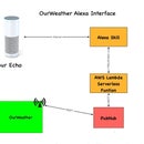
Introduction: Lightning! the Lightning Detector for Raspberry Pi Weather Station (Updated)


In this Instructable you will learn:
- How to a connect a Lightning Detector to a Solar Powered Weather Station
- How to design and position the lightning detector for best perfomance
- How to gather data to see the Lightning story as it happens
- How to wire up a the lightning detector to an I2C Mux and a Raspberry Pi
- Building 3D Printed Parts for the pylon to hold the Lightning Detector
- Examine the Python software for running the Lightning Detector on a Raspberry Pi
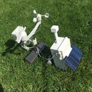
Recently, we published an Instructable detailing how to build a solar powered Raspberry Pi weather station, WeatherPi.
Updated: February 6, 2016: Changed to new I2C Mux Board. Grove 4 Channel I2C Mux Board.
What is Weather Pi?
WeatherPi is a solar powered Raspberry Pi WiFi connected weather station designed for Makers by SwitchDoc Labs. This is a great system to build and tinker with. All of it is modifiable and all source code is included. The most important functions are:
- Senses 20 different environmental values
- Completely Solar Powered
- Has a full database containing history of the environment (MySQL)
- Monitors and reports lots of data on the solar powered system - great for education!
- Self contained and monitored for brownouts and power issues
- Can be modified remotely
- Download your data to crunch it on your PC
- Can be modified to do SMS (Text) messaging, Twitters, webpages and more
- Has an iPad Based Control Panel
- Easy to connect to Twitter, WeatherUnderground, etc
Enter the Lightning
This Instructable will show you how to add an Embedded Adventures MOD-1016 AS3935 Lightning Detector Breakout Board to the Solar Powered Raspberry Pi Weather Station.
Follow along on updates to the WeatherPi story on www.switchdoc.com.
What is the AS3935 and How Does It Work?
The Austrian Microsystems AS3935 is a programmable Lightning Sensor IC that detects the presence and approach of potentially hazardous lightning activity in the vicinity and provides an estimation on the distance to the head of the storm. The embedded lightning algorithm checks the incoming signal pattern to reject the potential man-made disturbers and various noise sources.
The AS3935 can also provide information on the noise level and inform the Raspberry Pi of high noise conditions.
Step 1: Connect the Lightning Detector to WeatherPi


The complete Instructable for building WeatherPi, a solar powered Raspberry Pi based Weather Station, including the parts list and full wiring list is here.
Since we left our other MOD-1016 AS3935 breakout board on the WeatherPiArduino board for the time being, we decided to add an additional MOD-1016 AS3935.

Since the MOD-1016 has a fixed I2C address (0x03), we couldn't connect it up to the same I2C bus as the WeatherPiArduino board is on. So, using the I2C Multiplexer board, we put the second MO-1016 on bus 2.
We are always running into conflicts with addressing on the I2C device. Since there are no standards, sometimes multiple devices will have the same address, such as 0x03, and you are just out of luck in running both of them on the same I2C bus without a lot of jimmy rigging.

4 Channel Multiplexed I2C Breakout Board
To get around this addressing problem (specifically the conflict between an INA3221 and the Inside Humidity Sensor as well as having two identical lightning sensors - see below) we added an I2C Bus Multiplexer to the design which allows us to have many more I2C devices on the bus, irregardless of addressing conflicts. Below is our current list of I2C devices in WeatherPi.
| Module | Address | I2C Mux Bus # |
|---|---|---|
| BMP180 Barometric Pressure | 0x77 | Bus 0 |
| Real Time Clock DS3231 | 0x68 | Bus 0 |
| ATC EEPROM | 0x56 (or 0x57) | Bus 0 |
| ADS1015 Analog to Digital Converter | 0x49 | Bus 0 |
| FRAM non-volatile storage | 0x50 | Bus 0 |
| ADS1015 on SunAirPlus | 0x48 | Bus 1 |
| INA3221 3 Channel Voltage/Current Monitor on SunAirPlus | 0x40 | Bus 1 |
| Embedded Adventures Lightning Detector | 0x03 | Bus 0 |
| Embedded Adventures Lightning Detector | 0x03 | Bus 2 |
| AM2315 Outdoor Temp/Humidity | 0x5C | Bus 1 |
| Grove I2C 4 Channel I2C Bus Mux | 0x73 | On All Busses |
| HTU21D-F Humidity Sensor | 0x40 | Bus 0 |
Note that a number of devices have the same address. This is fixed by using the Grove I2C Mux Breakout Board.
Wiring List
These are just the additions to the wiring list for the AS3935 Breakout Board connected to Bus2 of the I2C Mux and placed in the 3D Printed Pylon. The full wiring list for WeatherPi is in the Instructable.
| Grove I2C Mux Board (GI2CM) | ||
|---|---|---|
| JP5 - I2C Bus2 | External AS3935 Breakout Board (ASBB) | |
| GI2CM JP5/Pin 3: VDU2 | 3.3V From Pi/Screw Connector | 3.3V From Pi/Screw Connector |
| GI2CM JP5/Pin 2: GND | ASBB: GND | GND for ASBB Board |
| GI2CM JP5/Pin 5: SC2 | ASBB: SCL | SCL for ASBB Board |
| GI2CM JP5/Pin 4: SD2 | ASBB: SDA | SDA for ASBB Board |
External AS3935 Breakout Board (ASBB) | ||
|---|---|---|
| External AS3935 Breakout Board (ASBB) | JP5 - I2C Bus2 | |
| ASBB: VCC | 3.3V From Pi/Screw Connector | 3.3V From Pi/Screw Connector |
| ASBB: GND | GI2CM JP5/Pin 2: GND | GND for ASBB Board |
| ASBB: SCL | GI2CM JP5/Pin 5: SC2 | SCL for ASBB Board |
| ASBB: SDA | GI2CM JP5/Pin 4: SD2 | SDA for ASBB Board |
| ASBB: IRQ | PiA+ GPIO/Pin 15: GPIO 22 | IRQ Line to Raspberry Pi |
Here is what the I2C bus looks like on the Raspberry Pi. This is the output from the example code with the I2C 4 Channel Mux (hence there are 4 independent busses shown for the I2C bus).
Note that WeatherPi uses Bus 0, Bus 1 and Bus 2.
Bus 2 is only used for connecting to the external MOD-1016 AS9535 Lightning detector. Running the test software for the I2C Mux Breakout Board gives the following results:
Test SDL_Pi_TCA9545 Version 1.0 - SwitchDoc Labs

Sample uses 0x73
Program Started at:2015-05-19 02:45:59

-----------BUS 0-------------------
addr = 0x73 returndata = 0x81
tca9545 control register B3-B0 = 0x1
ignore Interrupts if INT3' - INT0' not connected
tca9545 control register Interrupts = 0x8
     0  1  2  3  4  5  6  7  8  9  a  b  c  d  e  f
00:          03 -- -- -- -- -- -- -- -- -- -- -- --
10: -- -- -- -- -- -- -- -- -- -- -- -- -- -- -- --
20: -- -- -- -- -- -- -- -- -- -- -- -- -- -- -- --
30: -- -- -- -- -- -- -- -- -- -- -- -- -- -- -- --
40: 40 -- -- -- -- -- -- -- -- 49 -- -- -- -- -- --
50: 50 -- -- -- -- -- 56 -- -- -- -- -- -- -- -- --
60: -- -- -- -- -- -- -- -- 68 -- -- -- -- -- -- --
70: -- -- -- 73 -- -- -- 77

-----------------------------------

-----------BUS 1-------------------
addr = 0x73 returndata = 0xa2
tca9545 control register B3-B0 = 0x2
ignore Interrupts if INT3' - INT0' not connected
tca9545 control register Interrupts = 0xa
     0  1  2  3  4  5  6  7  8  9  a  b  c  d  e  f
00:          -- -- -- -- -- -- -- -- -- -- -- -- --
10: -- -- -- -- -- -- -- -- -- -- -- -- -- -- -- --
20: -- -- -- -- -- -- -- -- -- -- -- -- -- -- -- --
30: -- -- -- -- -- -- -- -- -- -- -- -- -- -- -- --
40: 40 -- -- -- -- -- -- -- 48 -- -- -- -- -- -- --
50: -- -- -- -- -- -- -- -- -- -- -- -- -- -- -- --
60: -- -- -- -- -- -- -- -- -- -- -- -- -- -- -- --
70: -- -- -- 73 -- -- -- --

-----------------------------------

-----------BUS 2-------------------
addr = 0x73 returndata = 0x84
tca9545 control register B3-B0 = 0x4
ignore Interrupts if INT3' - INT0' not connected
tca9545 control register Interrupts = 0x8
     0  1  2  3  4  5  6  7  8  9  a  b  c  d  e  f
00:          03 -- -- -- -- -- -- -- -- -- -- -- --
10: -- -- -- -- -- -- -- -- -- -- -- -- -- -- -- --
20: -- -- -- -- -- -- -- -- -- -- -- -- -- -- -- --
30: -- -- -- -- -- -- -- -- -- -- -- -- -- -- -- --
40: -- -- -- -- -- -- -- -- -- -- -- -- -- -- -- --
50: -- -- -- -- -- -- -- -- -- -- -- -- -- -- -- --
60: -- -- -- -- -- -- -- -- -- -- -- -- -- -- -- --
70: -- -- -- 73 -- -- -- --

-----------------------------------
Step 2: Testing the Lightning Unit


Not surprisingly, this lightning detection device is very sensitive to RFI (Radio Frequency Interference) sources. If you have your device next to a monitor, it will not work well. If you have it next to a cell phone, it will not work well. As you will see below, we had to mount the detector well away from the Raspberry Pi and Solar Power Controller to get it to work well.
When we found the AS3935 device, we were pretty excited about using it in a design. One of the issues we quickly found ourselves facing was how to test the AS3935 in our own design. As noted in a previous step, we could cause noise to happen by placing close to monitors and cell phones (which actually tests a lot of the hardware and software, but nothing really about sensitivity in a measured, calibrated way), but we wanted something more accurate to test it with. We could cause interrupts (mostly of the noise floor type), but few lightning bolts.
We ended up buying the AS3935 Touch Sensor Development Tools Franklin Lightning Sensor IC Development Kit from mouser.com. It set us back $230, which was more than we wanted to pay, but we quickly used it to diagnose a number of the problems in the design and the device placement.
As we were finishing this Instructable, an actual thunderstorm came by SwitchDoc Labs. Unfortunately, We had the AS3935 all taken apart in pieces, so we grabbed the development kit and turned it on and were quickly rewarded with a number of lightning bolt detections.

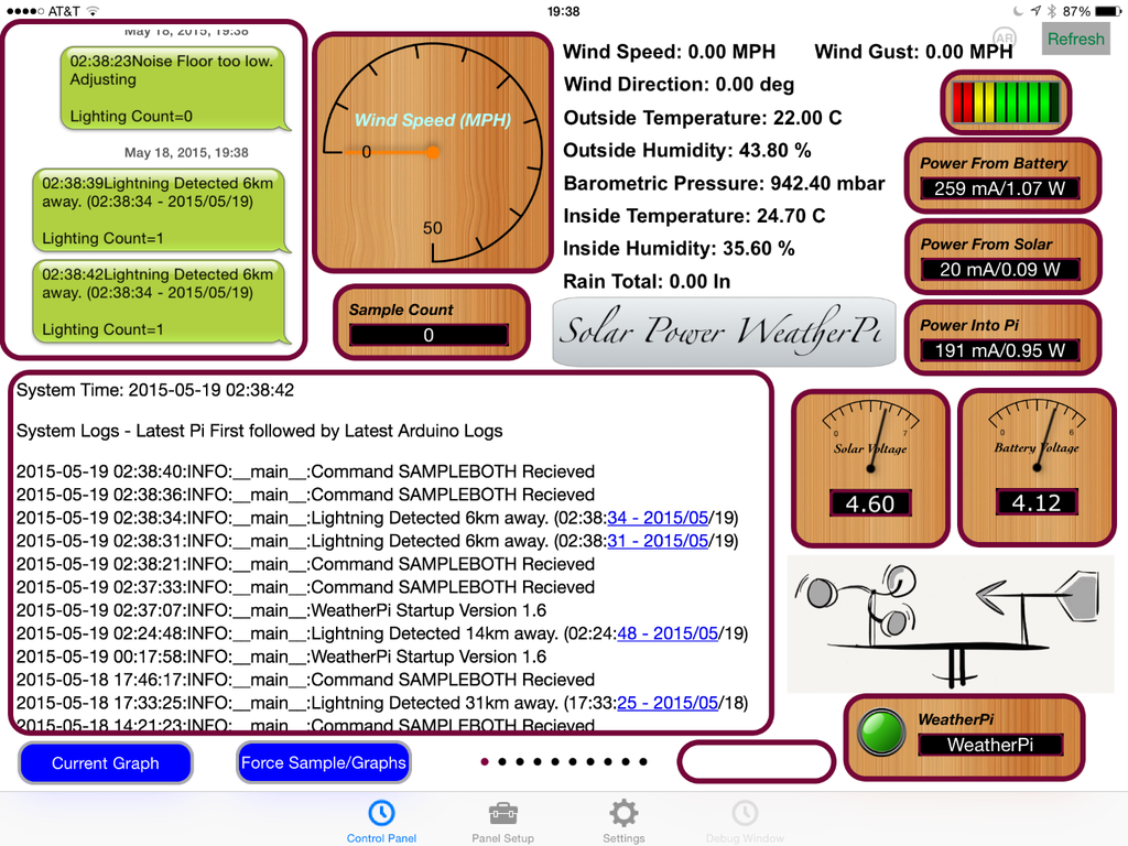
Later on in the weekend, a real thunderstorm rolled through about 6km away and produced this data, shown on RasPiConnect. The WLAN Down messages are from an ongoing problem with WiFi disconnects. We reset the WiFi dongle if there is a disconnect and log the event.

These detections were after we moved the lightning detector out into the pylon (actually, we just added another one rather than unsolder the one on the WeatherPiArduino - we will do that later next week).
Step 3: 3D Print Your Lightning Pylon


Problem Mounting the AS3935 Inside the Box
We installed the MOD-1016 containing the AS3935 on the header provided on the WeatherPiArduino board. You can see it installed in the center of the picture below.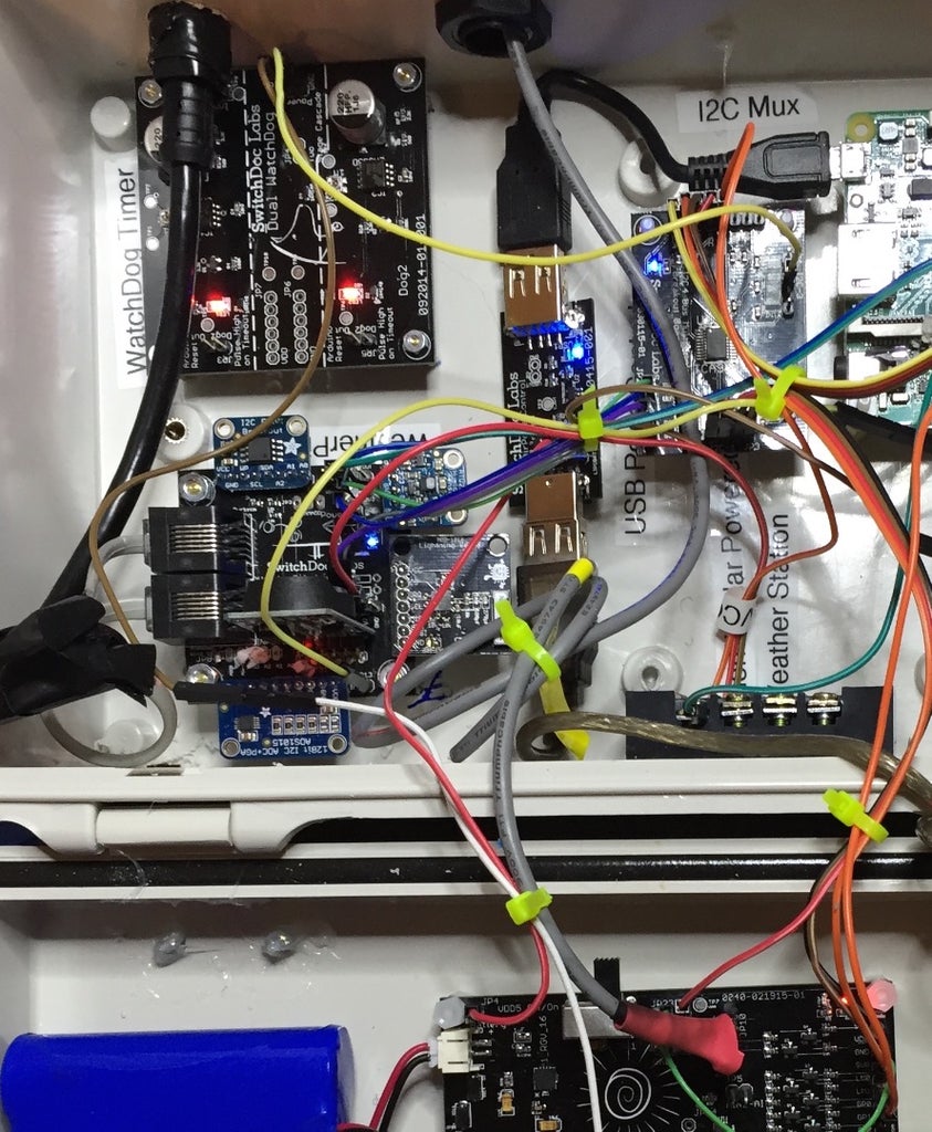
The AS3835 Breakout Board Installed on WeatherPiArduino
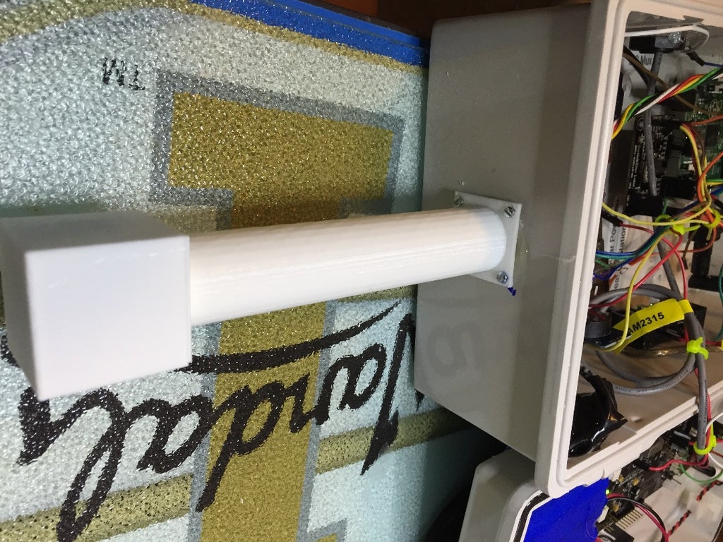
This turned out not to be a good location. Too much noise from all the other components surrounding it. We were getting interrupts telling us to adjust the noise floor and then you had to be right on top of it with the lightning simulator to get any response at all. We needed to move it away from the other electronics. In hindsight, we should have known that this would happen. The solution? Move it away from the box in a pylon. We thought of moving the WeatherPiArduino into a pylon, but we decided to just put an AS3835 in the pylon. See the 3D Print files above. Below is what the three parts look like on the screen in OpenSCAD and then it is followed by a picture of the pylon printed and installed on the WeatherPi Box. Here are the OpenSCAD files for the pylon.
The 3D Printed Parts of the Lightning Pylon

Step 4: The Software for the Lightning Detector


After quite the search and playing with a number of packages, we found a good package by Phil Fenstermacher. With a little fooling around and setting up interrupts, we got the software to work.
The full software for WeatherPi, which includes the AS3935 software is available on github.com.
Here is the setup software:
################

# ad3935 Set up Lightning Detector

# turn I2CBus 2 on
tca9545.write_control_register(TCA9545_CONFIG_BUS2)
time.sleep(0.003)
#tca9545.write_control_register(TCA9545_CONFIG_BUS0)
#time.sleep(0.003)

as3935 = RPi_AS3935(address=0x03, bus=1)

as3935.set_indoors(False)
as3935.set_noise_floor(0)
#as3935.calibrate(tun_cap=0x0F)
as3935.calibrate(tun_cap=0x05)

as3935LastInterrupt = 0
as3935LightningCount = 0
as3935LastDistance = 0
as3935LastStatus = ""

as3935Interrupt = False
# turn I2CBus 0 on
tca9545.write_control_register(TCA9545_CONFIG_BUS0)
time.sleep(0.003)
Next the processing software for the Interrupts.
def process_as3935_interrupt():

    global as3935Interrupt
    global as3935, as3935LastInterrupt, as3935LastDistance, as3935LastStatus

    as3935Interrupt = False

    print "processing Interrupt from as3935"
    # turn I2CBus 0 on
    #tca9545.write_control_register(TCA9545_CONFIG_BUS0)
    # turn I2CBus 2 on
    tca9545.write_control_register(TCA9545_CONFIG_BUS2)
    time.sleep(0.003)
    reason = as3935.get_interrupt()

    as3935LastInterrupt = reason

    if reason == 0x00:
        as3935LastStatus = "Spurious Interrupt"
    elif reason == 0x01:
        as3935LastStatus = "Noise Floor too low. Adjusting"
        as3935.raise_noise_floor()
    elif reason == 0x04:
        as3935LastStatus = "Disturber detected - masking"
        as3935.set_mask_disturber(True)
    elif reason == 0x08:
        now = datetime.now().strftime('%H:%M:%S - %Y/%m/%d')
        distance = as3935.get_distance()
        as3935LastDistance = distance
        as3935LastStatus = "Lightning Detected "  + str(distance) + "km away. (%s)" % now
        pclogging.log(pclogging.INFO, __name__, "Lightning Detected "  + str(distance) + "km away. (%s)" % now)

    print "Last Interrupt = 0x%x:  %s" % (as3935LastInterrupt, as3935LastStatus)
    tca9545.write_control_register(TCA9545_CONFIG_BUS0)

    time.sleep(0.003)
The Interrupt Handler. Short and Sweet, as interrupt handlers should be. def handle_as3935_interrupt(channel):
global as3935Interrupt
print "as3935 Interrupt"
as3935Interrupt = True
Setting up the Raspberry Pi GPIOs to receive interrupts. #as3935pin = 18 as3935pin = 22 GPIO.setup(as3935pin, GPIO.IN) #GPIO.setup(as3935pin, GPIO.IN,pull_up_down=GPIO.PUD_UP) GPIO.add_event_detect(as3935pin, GPIO.RISING, callback=handle_as3935_interrupt)
And the reporting software for reading the Interrupts.
        # process Interrupts from Lightning

        if (as3935Interrupt == True):

                try:
                        process_as3935_interrupt()


                except:
                        print "exception - as3935 I2C did not work"
Step 5: See the Real Results!


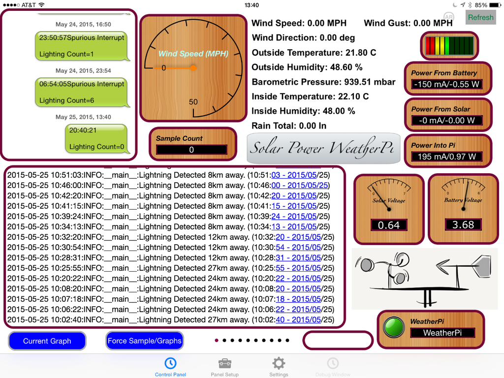
We have been running the AS3935 breakout board in the WeatherPi pylon for the past 5 days. We have had two thunderstorms come through during that time. The first storm was pretty week and just moved through north of SwitchDoc Labs. Our president, Laurel, was out playing golf (the benefits of power and position) and she called us to tell us that the lightning storm had come by, and we got to tell her that we already knew. Below are the lightning logs from our RasPiConnect control panel. Note that there was no wind measured during as we had the WeatherRack Weather Sensors disconnected as it was plugged into Project Curacao (and did pick up the wind), which is heading to the tropics shortly.
Next up was a big storm two days later that really rocked! You can see (reading the log backwards according to UTC timestamp) the storm approach and then go by and depart. Came within 6km of SwitchDoc Labs.

And it texts us reports too!
Step 6: Conclusion


Adding the lighting detector to the solar powered WeatherPi turned out to be quite straightforward in terms of software and wiring, but the real key to making it work was placing the sensor away from all the other electronics.
Our next project, a solar powered semi-autonomous robot called SunRover is also using this sensor. We will mount it in a pylon that is far away from the three computers in SunRover and especially away from the Raspberry Pi 2 (which is the main brain of the robot).
Here are some additional ideas for projects based on the WeatherPi Lightning Detection system:
- Replacing the WiFi with a GSM data connection (or just send text messages) Make it tweet lightning warnings! Make a custom Facebook posting with your lightning strikes
- Adding a GPS receiver and store that data
- You now have a mobile lightning detection system! When it gets back to WiFi all the stored data will be available.
- Connect to the WeatherUnderground or similar services


