

Introduction: Line Follower Robot - PID Control - Android Setup


==> This project won the 2nd prize at 2016 Robotics Contest at Instructables.com. Thanks a lot for all votes ;-)
The purpose of this project is to build a Line Follower Robot with PID control. We will also use an Android device to easily setup the main control parameters for better and fast tuning.
This project is the first of a 2 parts more complex project where my intention is to explore the potentiality of Line Follower Robots. On the 2nd part : Maze Solver Robot, using Artificial Intelligence with Arduino, the robot will explore and solve Mazes, using simple artificial intelligence techniques.
Bellow a video showing the robot following a line circuit:
Step 1: Bill of Material
The list of materials needed is very simple and the final robot is very cheap (around $ 75.00):
- Body (can be adapted for your needs):
- 2 Wood squares (80X80mm)
- 3 Binder clips
- 2 Wood wheels (diameter: 50mm)
- 1 Ball caster
- 9 Elastic bands
- 3M Command frame strip
- Plastic joints for sensor fix
- BreadBoard and wiring
- 2 sets of 4XNi-Metal Hydride Battery (5V each set)
- 2 X SM-S4303R Continuous Rotation 360 Degree Plastic Servo
- Arduino Nano
- HC-06 Bluetooth module
- 5 X Line sensors (TCRT5000 4CH Infrared Line Track Follower Sensor Module + 1 independent Track sensor)
- 1 LED
- 1 button
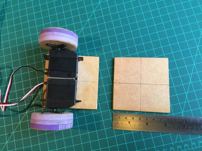
Step 2: Setting the Motors


For motors, 2 continuous servos (SM-S4303R) were used. They will be "glued" together making a single and solid block as you can see at the photo (use the 3M Command strip, glue or double face tape). Those servos will run on a given speed, defined by the pulse width received on its data input. For this specific servo, the pulse width goes from 1.0ms (1,000 microseconds) to 2.0ms (2,000 microseconds). Other servos can work with different pulse width.
Looking in details:
- A pulse of 1.5ms will position the servo at neutral position, or ”stopped”.
- A pulse of 1.0ms will command the servo to full speed (around 70 RPM) in one direction
- A pulse of 2.0ms full speed in the opposite direction.
- Pulse between 1.0 and 1.5ms or 1.5ms and 2.0ms, will generate proportional speed.
Once you have both servos physical connected, follow the drawing circuit above to source them (external 5V or 6V) and feed them with Arduino's signal:
- Left Servo: Arduino Pin 5
- Right Servo: Arduino Pin 3
Once all connected, the first thing that must be done, is to send a 1.5ms pulse to verify if the motors are "stopped" (not running). If not, the servos must be adjusted to full stop (look for the yellow bolt, bellow the servo). NOTE: If your servo does not have this phisical adjustment, try to change the parameter "1500" microsecond inside the function (up or down) until you get the full stop.
The Arduino code bellow can do the job:
#include <Servo.h> // Servo library
Servo leftServo;
Servo rightServo;

Void setup()
{
  leftServo.attach(5);
  rightServo.attach(3);
  leftServo.writeMicroseconds(1500);
  rightServo.writeMicroseconds(1500);
}

void loop()
{
}
Step 3: Assembly the Body and Motors for Movement Test

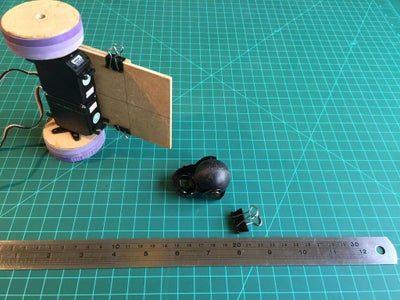


- With the 3M Command frame strip, fix the 2 Servos to the one of the squared wood piece.
- Fix the 2nd squared wood to the above one using the Binder Clips. Adjust the length of the platform to your needs.
- Fix the Ball Caster using the Binder Clip.
- The Power Supply for the motors will come from one of the 5V set of batteries. This set of battery will be installed between the breadboard and the body frame.
- Connect the Battery to be used with servos: Left one of lateral power grid exclusively for servos source
- Connect the Arduino Nano to the breadboard
- Connect the GND of Power Grid to Arduino GND.
- Connect the Servos to Arduino: LEFT ==> Pin 5; RIGHT ==> Pin 3
- Connect the LED to Arduino Pin 13
- Connect the button to Arduino Pin 9
Note that due the way that the servos are mounted (in opposition) the speed range is:
- Right Servo forward speed goes from 1,500us (stopped) to 2,000us (full speed)
- Left Servo forward speed goes from 1,500us (stopped) to 1,000 (full speed)
An external LED is add to pin13, for signalization and test purposes (you can use the internal Arduino LED, instead an external if you want, but take in consideration that will be hard to see it in the middle of the cables).
Also a button is connected to pin 9. This button is very useful for test purposes and for robot's start.
For example:
while(digitalRead(buttonPin))
{
}
motorTurn (LEFT, 500);
motorTurn (RIGHT, 500);
Note that the 2 lines that will command the Robot to turn LEFT, wait 500ms and turn RIGHT only will happen after you press the button (buttonPin = 0). Before that, the program will be stopped in the infinite loop.
The code bellow, can be used as a base for a complete motor test (Forward, Backward, Full stop, Turn Left, Turn Right). If necessary you must adjust the delays for the required turn angle depending of your motors (also, sometimes left and right pulse values should be a little bit different to compensate any lack of balance of the motors.
Attachments

Step 4: The Bluetooth Module (optional)


The Bluetooth module HC-06 should be installed at breadboard as shown in the draw. The Arduino library SoftSerial will be used.
Below the HC-06 pin connections:
- Tx Pin to Arduino pin 10 (Rx)
- RX Pin to Arduino pin 11 (Tx)
- VCC/GND to Arduino 5V/GND
The Robot will work with or w/o the Bluetooth. The code is built on a way that if you do not activate the BT, the default parameters will be the one to be used by the robot. So, do not worry if you prefer do not install the HC-06 module, the code still will work fine. In the last part of this tutorial, I will explore how to use an Android App for sending data for better tuning of the robot parameters and/or move the robot in manual mode. I will leave the use of the Bluetooth and the App as an optional in case someone would like to explore more the use a Line Follower Robot for competitions, for example.
Step 5: Adding the Line Sensors


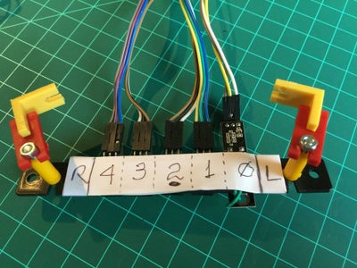


- Fix the 5 sensors on a plastic bar as shown at the photos
- It is advisable to label the sensors for test purposes. The sensors name goes from from "0" (more to the Left) to "4" (more to the Right)
- Run the cables under the frame, using the elastic bands to fixed them (take care not to mix-up with the wheels or Caster.
- Connect the cables to Arduino pins as bellow:
- Sensor 0 = 12
- Sensor 1 = 18
- Sensor 2 = 17
- Sensor 3 = 16
- Sensor 4 = 19
- Fixed the second set of 5V batteries and connect it to Arduino Vin.
In my case I use a module with 4 sensors integrated + 1 extra. All of then are compatible. For simplicity, in the diagram I included 5 stand-alone sensors connect together. The final result are the same in both configurations.
Step 6: Implementing the IR Sensor Logic


The IR sensor consists of an individual IR LED and an IR Photodiode. The IR light emitted by the LED strikes the surface and is reflected back to the IR Photodiode. The photodiode then generate an output voltage proportional to the reflectance level of the surface (higher values for "light surfaces" and lower for "black/dark surfaces").
In the case of the sensors used, an integrated circuit at the module generates as output a simple digital signal (HIGH: Dark; LOW: Light). A potentiometer installed at the module (see photo) will adjust the correct level of light to be considered "dark" or "light". It works on a way that when the reflected light color is black/dark, a HIGH ("1") digital level is generated at its output and a LOW ("0") for another lighter color. I used here a integrated module with 4 sensors and and extra module with a sole sensor (different shape, but same logic). The combination is an array of 5 sensors that i found is good for a nice and smooth control, as explained bellow.
The array of 5 sensors is mounted on a way that if only one sensor is centered with relation to the black line, only that specific sensor will produce a HIGH. By other side, the space between sensors should be calculated to allow that 2 sensors can cover the full width of the black line simultaneously, producing also a HIGH on both sensors (see the pictures above).
The possible sensor array output when following a line are:
- 0 0 0 0 1
- 0 0 0 1 1
- 0 0 0 1 0
- 0 0 1 1 0
- 0 0 1 0 0
- 0 1 1 0 0
- 0 1 0 0 0
- 1 1 0 0 0
- 1 0 0 0 0
Having 5 sensors, permits a generation of an "error variable" that will help to control the robot's position over the line, as shown bellow.
Let's consider that the optimum condition is when the robot is centered, having the line just bellow the "middle sensor" (Sensor 2). The output of the array will be: 0 0 1 0 0 and in this situation, the "error" will be "zero". If the robot starts to driven to the left (the line "seems move" right") the error must increase with a positive signal. If the robot start to move to the right (the line "seems move" left"), in the same way, the error must increase, but now with a negative signal.
The error variable, related with the sensor status will be:
- 0 0 0 0 1 ==> Error = 4
- 0 0 0 1 1 ==> Error = 3
- 0 0 0 1 0 ==> Error = 2
- 0 0 1 1 0 ==> Error = 1
- 0 0 1 0 0 ==> Error = 0
- 0 1 1 0 0 ==> Error = -1
- 0 1 0 0 0 ==> Error = -2
- 1 1 0 0 0 ==> Error = -3
- 1 0 0 0 0 ==> Error = -4
Looking at the Arduino code, each one of the sensors will be defined with a specific name (consider that the Line Follow Sensor more to the Left must be assigned with a label "0"):
const int lineFollowSensor0 = 12;
const int lineFollowSensor1 = 18;
const int lineFollowSensor2 = 17;
const int lineFollowSensor3 = 16;
const int lineFollowSensor4 = 19;
In order to storage the values of each sensor an array variable will created:
int LFSensor[5]={0, 0, 0, 0, 0};
Each position of the array will be constantly updated with the output of each one of the sensors:
LFSensor[0] = digitalRead(lineFollowSensor0);
LFSensor[1] = digitalRead(lineFollowSensor1);
LFSensor[2] = digitalRead(lineFollowSensor2);
LFSensor[3] = digitalRead(lineFollowSensor3);
LFSensor[4] = digitalRead(lineFollowSensor4);
Having the value of each one of the sensors, a logic must be implemented to generate the error variable:
if((LFSensor[0]== 0 )&&(LFSensor[1]== 0 )&&(LFSensor[2]== 0 )&&(LFSensor[3]== 0 )&&(LFSensor[4]== 1 )) error = 4;

else if((LFSensor[0]== 0 )&&(LFSensor[1]== 0 )&&(LFSensor[2]== 0 )&&(LFSensor[3]== 1 )&&(LFSensor[4]== 1 )) error = 3;

else if((LFSensor[0]== 0 )&&(LFSensor[1]== 0 )&&(LFSensor[2]== 0 )&&(LFSensor[3]== 1 )&&(LFSensor[4]== 0 )) error = 2;

else if((LFSensor[0]== 0 )&&(LFSensor[1]== 0 )&&(LFSensor[2]== 1 )&&(LFSensor[3]== 1 )&&(LFSensor[4]== 0 )) error = 1;

else if((LFSensor[0]== 0 )&&(LFSensor[1]== 0 )&&(LFSensor[2]== 1 )&&(LFSensor[3]== 0 )&&(LFSensor[4]== 0 )) error = 0;

else if((LFSensor[0]== 0 )&&(LFSensor[1]== 1 )&&(LFSensor[2]== 1 )&&(LFSensor[3]== 0 )&&(LFSensor[4]== 0 )) error =- 1;

else if((LFSensor[0]== 0 )&&(LFSensor[1]== 1 )&&(LFSensor[2]== 0 )&&(LFSensor[3]== 0 )&&(LFSensor[4]== 0 )) error = -2;

else if((LFSensor[0]== 1 )&&(LFSensor[1]== 1 )&&(LFSensor[2]== 0 )&&(LFSensor[3]== 0 )&&(LFSensor[4]== 0 )) error = -3;

else if((LFSensor[0]== 1 )&&(LFSensor[1]== 0 )&&(LFSensor[2]== 0 )&&(LFSensor[3]== 0 )&&(LFSensor[4]== 0 )) error = -4;
Step 7: Controlling Direction (Proportional Control - P)
Perfect! At this point, our Robot is assembled and operational. You should perform some basic tests with the motors, read the output of sensors and testing them over a line. What is missing is the real "brain", the first steps of an "artificial intelligence". We will get this, implementing a control logic that will guarantee that the Robot will be kept following the line.
Simple Proportional Control:
Suppose that the Robot is running over a line and the Sensor Array output is: "0 0 1 0 0 ". The correspondent error is "0". in this situation, both motors should be running forward with constant speed.
For example:
Defining the variable:iniMotorSpeed = 250; means that LEFT servo will receive pulses of 1,250us and RIGHT servo, 1,750us. With those parameters, the Robot will move forward at half speed. Remember that the RIGHT servo Forward speed will range with pulse length from 1,500us (stopped) to 2,000us (full speed) and the LEFT servo from 1,500us (stopped) to 1,000us (full speed).
rightServo.writeMicroseconds(1500 + iniMotorPower);
leftServo.writeMicroseconds(1500 - iniMotorPower);
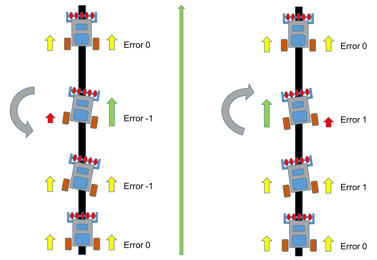
Suppose now that the Robot driven to the left (it is like the "LINE goes to right") and covered also the sensor 3. The Array output will be: "0 0 1 1 0 " and the error = 1. In this situation what you need is turn the Robot to the right. To do that, you must decrease the speed of RIGHT servo what means decrease the length of the pulse. Also, the speed of LEFT servo must increase, what means decrease the length of the LEFT servo pulse. To do that, we need to change the motor control function:
rightServo.writeMicroseconds(1500 + iniMotorPower - error); ==> Positive error: decrease velocity
leftServo.writeMicroseconds(1500 - iniMotorPower - error); ==> Positive error: increase velocity
The above logic is correct, but it is ease to understand that adding or subtracting "1" microsecond at pulse length will not generate the required correction on a realistic time. It is intuitive that the number to be add or subtracted should be greater, for example 50, 100, etc. To get that, the "error" must be multiplied by a constant (let's call it "K"). Once the influence of this constant will be proportional to the error, we will name it "Proportional Constant: Kp.
The motor function will be:
int Kp = 50;
rightServo.writeMicroseconds(1500 + iniMotorPower - Kp*error);
leftServo.writeMicroseconds(1500 - iniMotorPower - Kp*error);
We can resume what will happen with the motors as shown bellow:
- Sensor Array: 0 0 1 0 0 ==> error = 0 ==> Right Servo pulse length = 1,750us ==> Left Servo pulse length = 1,250us (both motors at same speed)
- Sensor Array: 0 0 1 1 0 ==> error = 1 ==> Right Servo pulse length = 1,700us (slower) ==> Left Servo pulse length = 1,200us (faster)
If the situation is the opposite and the Robot driven to the right, the error would be "negative" and the speed of the servos should change:
- Sensor Array: 0 0 1 0 0 ==> error = 0 ==> Right Servo pulse length = 1,750us ==> Left Servo pulse length = 1,250us (both motors at same speed)
- Sensor Array: 0 1 1 0 0 ==> error = -1 ==> Right Servo pulse length = 1,800us (faster) ==> Left Servo pulse length = 1,300us (slower)
At this point is clear that as much the Robot driven to one side, bigger will be the error and faster it must return to center. The velocity with the Robot will react to the error will be proportional to it. This is called "Proportional Control ", that is the "P" component of a more complex control network, the PDI (Proportional, Derivative, Integral).
Step 8: PID Control (optional)


In case you want jump this part, it is also OK. You can stay with the Proportional control explained on the last step, or burn some brains to implement a more complex Control system in your Robot, it is your choice.
If you made your mind, let's go!
PID (Proportional, Derivative and Integral) is one of the most common control schemes around. Most industrial control loops use some flavor of PID control. There are many ways to tune a PID loop, including the manual technique used in this example.
Think of PID as a simple spring. A spring has an original length, which when disturbed by expansion or contraction, tends to regain its original length in the shortest possible time. Similarly, a PID algorithm in a system has a set-value of a particular physical quantity to be controlled, called a ‘set point’, which when altered due to some reason, the system controls the other necessary features in it, to get back to the original set point in the shortest time possible. PID controllers are used wherever there is a need to control a physical quantity and to make it equal to a specified value. Example, Cruise Controller in cars, Robots, Temperature regulators, Voltage regulators, etc.
How does PID work?
The system calculates the ‘error’, or ‘deviation’ of the physical quantity from the set point, by measuring the current value of that physical quantity using a sensor(s). To get back to the set point, this ‘error’ should be minimized, and should ideally be made equal to zero. Also, this process should happen as quickly as possible. Ideally, there should be zero lag in the response of the system to the change in its set point.
More information can be found in many books and websites, including here:
http://en.wikipedia.org/wiki/PID_controller
Implementing PID
i) Error Term (e):
This is equal to the difference between the set point and the current value of the quantity being controlled.
error = set_point – current_value (in our case is the error variable get from the position of Robot over the line
ii) Proportional Term (P):
This term is proportional to the error.
P = error
This value is responsible for the magnitude of change required in the physical quantity to achieve the set point. The proportion term is what determines the control loop rise time or how quickly it will reach the set point.
iii) Integral Term (I):
This term is the sum of all the previous error values.
I = I + error
This value is responsible for the quickness of response of the system to the change from the set point. The integral term is used the eliminate the steady state error required by the proportional term. Usually, small Robots doesn't use the integral term because we are not concerned about steady state error and it can complicate the "loop tuning".
iv) Differential or Derivative Term (D):
This term is the difference between the instantaneous error from the set point, and the error from the previous instant.
D = error - previousError
This value is responsible to slow down the rate of change of the physical quantity when it comes close to the set point. The derivative term is used to reduce the overshoot or how much the system should "over correct".
Equation:
PIDvalue = (Kp*P) + (Ki*I) + (Kd*D)
Where:
- Kp is the constant used to vary the magnitude of the change required to achieve the set point.
- Ki is the the constant used to vary the rate at which the change should be brought in the physical quantity to achieve the set point.
- Kd is the constant used to vary the stability of the system.
One approach to tune the loop can be Try-error tentative metod:
- Set the Kd variable to 0 and tune the Kp term alone first. Kp of 25 is a good place to start in our case here. At last step we used a Kp of 50 that works very well with my Robot.
- If the robot reacts too slowly, increase the value.
- If the robot seems to react fast becoming unstable, decrease the value.
- Once the robot responses reasonably, tune the derivative portion of the control loop (Kd). First set the Kp and Kd value each to the 1/2 of the Kp value. For example, if the robot responses reasonable with a Kp = 50, then set Kp = 25 and Kd = 25 to start. Increase the Kd (derivative) gain to decrease the overshoot, decrease it if the robot become unstable.
One other component of the loop to consider is the actual Sample/Loop Rate. Speeding this parameter up or slowing this down can make a significant difference in the robot's performance. This is set by the delay statements that you have in your code. It is a Try-error tentative metod to get the optimum result
Based on the above approach, the bellow function was implemented:
void calculatePID()
{
  P = error;
  I = I + error;
  D = error-previousError;
  PIDvalue = (Kp*P) + (Ki*I) + (Kd*D);
  previousError = error;
}
The simple Kp constant used on the last step will be replaced for this more complete PIDvalue:
void motorPIDcontrol()
{
  int leftMotorSpeed = 1500 - iniMotorPower - PIDvalue;
  int rightMotorSpeed = 1500 + iniMotorPower - PIDvalue;

  leftServo.writeMicroseconds(leftMotorSpeed);
  rightServo.writeMicroseconds(rightMotorSpeed);
}
But note that if you have Kd and Ki =0, PIDvalue is only Kp*error used in the last step
Step 9: The Final Code


At this step, the Robot can follow a constant loop and will do it w/o stop.
The loop program would be:
void loop ()
{
  readLFSsensors(); // read sensors, storage values at Sensor Array and calculate "error"
  calculatePID();
  motorPIDcontrol();
}
But for a more complete and real operation, It is important to add at least a couple of basics "commands" done "with the line". For example, let's introduce a new variable: "mode". We will define 3 states for this variable:
mode:
- #define STOPPED 0
- #define FOLLOWING_LINE 1
- #define NO_LINE 2
If all sensors find a black line, the Sensor Array output would be: 1 1 1 1 1. In this condition, we can define mode as "STOPPED" and the the Robot should perform a "full stop".
if((LFSensor[0]== 1 )&&(LFSensor[1]== 1 )&&(LFSensor[2]== 1 )&&(LFSensor[3]== 1 )&&(LFSensor[4]== 1 ))
{
  mode = STOPPED;
}
Other common situation with Follower Line Robots is where it founds "no line", or the Sensor Array output is: 0 0 0 0 0. In this case we can program it to turn back 180o or turn in small angles until a line is find and the normal Line Follow condition is resumed.
else if((LFSensor[0]== 0 )&&(LFSensor[1]== 0 )&&(LFSensor[2]== 0 )&&(LFSensor[3]== 0 )&&(LFSensor[4]== 0 ))
{
  mode = NO_LINE;
}
The complete loop () would be:
void loop()
{
  readLFSsensors();
  switch (mode)
  {
    case STOPPED:
       motorStop();
       break;
    case NO_LINE:
       motorStop();
       motorTurn(LEFT, 180);
       break;
    case FOLLOWING_LINE:
       calculatePID();
       motorPIDcontrol();
       break;
  }
}
The real final code will integrated some additional logic and also some variables that must be initialized, etc. During the above explanation I left them out for simplicity, but everything should be clear looking at final code.
Bellow the final Arduino Code:
Step 10: Tuning the PID Control Using the Android App


In the previous code, you can find at "robotDefines.h" tab the following definitions for the constants to be used with the PID control:
float Kp=50;
float Ki=0;
float Kd=0;
As explained at previous step, the best way to define the correct constant to be used with a PID controller is using the "Try-error" methodology. The bad side of that is that you must re-compile the program each time that you must change it. One way to speed-up the process is to use the Android App to send the constants at the "Set-Up Phase".
I developed an Android App exclusively for that. in short:
- There are the traditional manual commands:
- FW, BW, Left, Right and Stop where the app will send respectively to the BT module: 'f', 'b', 'l', 'r' and 's'.
- Also 3 sliders was included, one for each PID constants:
- Kp: "p/XXX"
- Ki: "i/XXX"
- Kd: "d/XXX"
- Where "XXX" it is a number from 0 to 100.
- An extra button was included that will work exactly as the button connected on Arduino Pin9. You can use one or the other, does not matter.
Bellow you can find the .aia file that can be modified at MIT AppInventor and the .apk file to be installed directly in your Android device.
Step 11: Changing the Code for PID Remote Tuning
During the Setup, we will introduce a loop where you can send the PID parameters to the Robot before you put him over the line:
  while (digitalRead(buttonPin) && !mode)
  {
    checkBTcmd();  // verify if a comand is received from BT remote control
    manualCmd ();
    command = "";
  }
  checkPIDvalues();
  mode = STOPPED;
The manual command function will be:
void manualCmd()
{
  switch (command[0])
  {
    case 'g':
      mode = FOLLOWING_LINE;
      break;

    case 's':
      motorStop(); //turn off both motors
      break;

    case 'f':
      motorForward();
      break;

    case 'r':
      motorTurn(RIGHT, 30);
      motorStop();

      break;

   case 'l':
      motorTurn(LEFT, 30);
      motorStop();
      break;

    case 'b':
      motorBackward();
      break;

    case 'p':
      Kp = command[2];
      break;

    case 'i':
      Ki = command[2];
      break;

    case 'd':
      Kd = command[2];
      break;
  }
}
In the video, you can see some tests using the Android App:
Bellow the final code including the PID setup via Android:
Step 12: Conclusion

This is the first of a more complex project, exploring the potentiality of a line follower robot. In the next part, I will develop a Maze solve robot, based on this this project here.
Hope I can contribute for others to learn more about electronics, robot, Arduino, etc.
The update files for this project can be found at GITHUB:
https://github.com/Mjrovai/MJRoBot-Line-Follower
For more tutorials, please visit my Blog:
Greetings from the south of the world!
Thanks
Marcelo

Second Prize in the
Robotics Contest 2016


