

Introduction: Line Following Robot
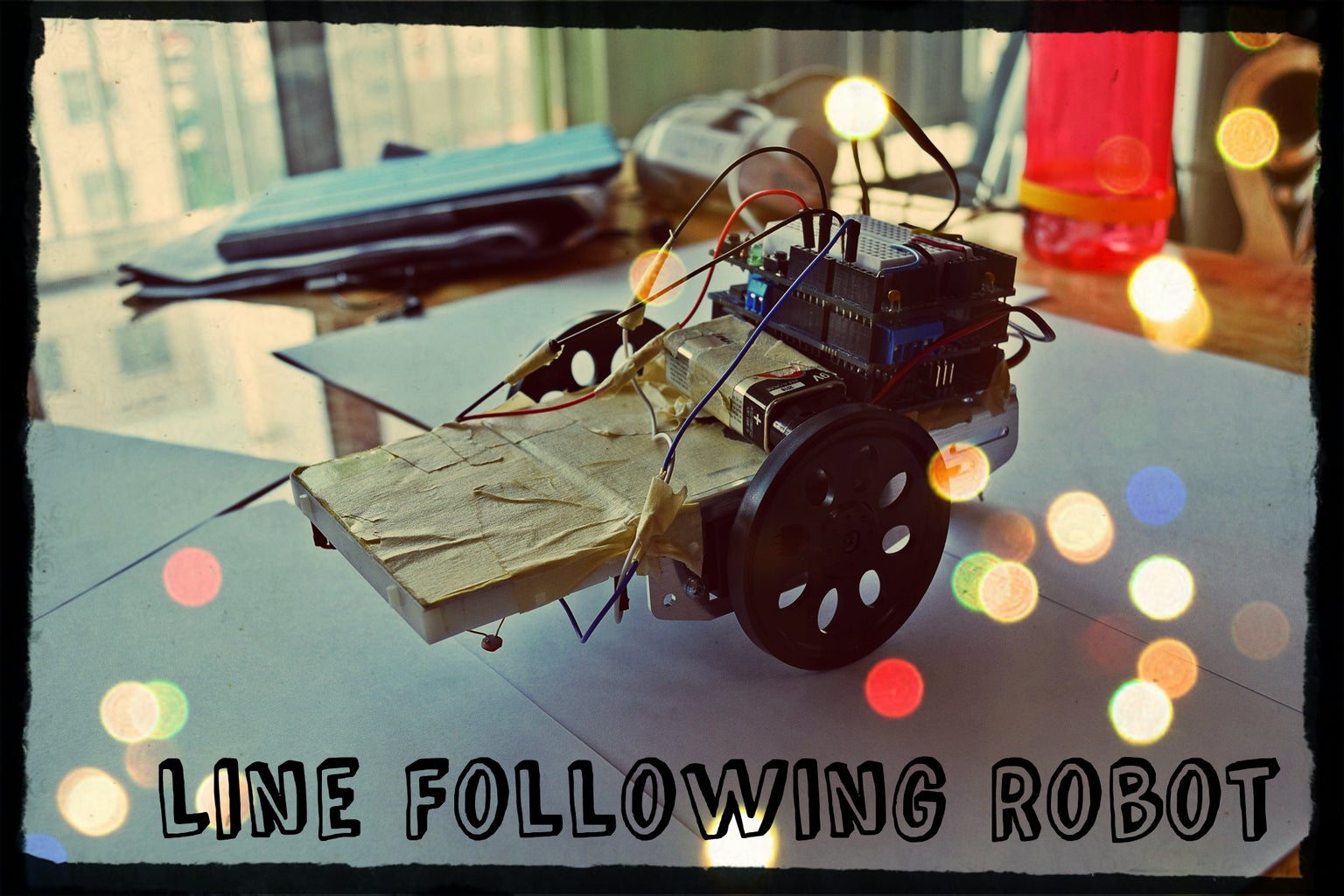


This is a Line Following Robot. It follows a black line that is drawn. It is able to detect the black line through one photocell and one analog light sensor. There is an LED in between the two sensors that gives off red light when the Arduino is powered on. Then, when the light is reflected back, more light is detected when it is reflected on the white surface, compared to when it is reflected on the black surface. Using this, the right and left servo motors move accordingly to turn left or right when the sensors detect white surface rather than black. I used the Parallax BOEBot Robot for Arduino Kit as my base for the robot. Then I placed a breadboard in front of the base to attach all the sensors with the LED to face the black line.
Follow these steps, and you will be able to build your own line following robot! :)
Step 1: Step 1: Parts


Parts needed:
- Arduino
- Motor Shield (https://www.adafruit.com/products/1438)
- LED with 100 ohms resistor
- Photo cell with 1K ohms resistor (https://www.adafruit.com/products/161)
- GA1A12S202 Log-scale Analog Light Sensor (https://www.adafruit.com/products/1384)
- A base for the robot with 2 wheels attached to servo motors ** I used : Parallax BOEBot Robot for Arduino Kit (https://www.adafruit.com/products/749)
- A breadboard
- A battery with a battery holder
- Black marker or black tape with white papers
- Tape to tape all the parts together
- Wire to connect all the parts (also jumper wires)
Step 2: Step 2: Assemble 1

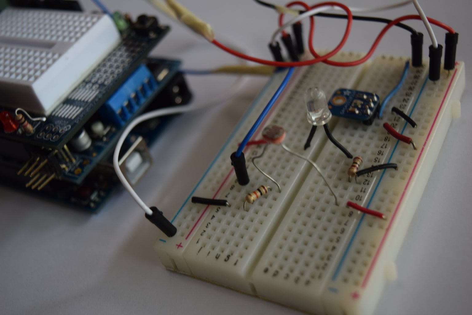


First, hook up all the sensors!
Connect the photo cell. One end should go to power and the other should connect to the 1K ohms resistor. Then, on the side with the photo cell and the resistor, connect to the analog pin. Next, connect the other end of the resistor to ground. Then connect the LED with the 100 ohm resistor on the breadboard. Finally connect the light sensor to the breadboard according to the label: ground, power, and one analog pin. Then connect all the wires with jumper wires to the Arduino. Make sure that your jumper wires are long enough to reach the Arduino on the base of the robot.
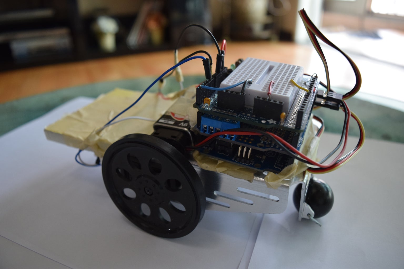
Second, attach the breadboard to the base of the robot.
I used tape since I couldn't really think of anything else, but you can use anything if it is going to be able to attach the breadboard (facing down) to the robot. Then, use more tape to organize the jumper wires.
Step 3: Step 3: Assemble 2


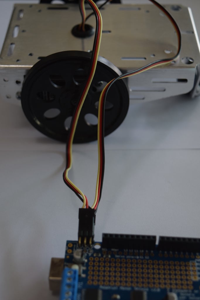


Third, prepare the base of the robot with the motor shield.
I had to screw in the servo motors to the right position. Then, screw in the wheels on the servo motors. To attach the servo motors, find the two servo pins on the corner of the motor shield. Connect the servo motors to the 2 pins. Note the servo number written on the motor shield according to which side of the motor it is attached to (right or left). Then organize the wires around the base so it would not get in the way of the wheels.
Lastly, make the track for the robot.
I used a black marker that I previously owned to draw the black line. To make the line more precise, I first taped the track with the tape that I owned, then I colored the tape with my black marker. Then, I taped the different white papers around to draw a semi-circle track.
Now, you are done! :)
Step 4: Step 4: Code

You can find the code at: http://ardututes.weebly.com/line-following-robot.h...
When working with the code, you will need to adjust the values for the photocell and the light sensor to change directions. To do this, just place the robot with the sensor (comment out the 2 lines of code to attach the servos in the setup) and check the values of the photocell and the light sensor when it is in the middle, right, and left edge of the black line. Then, change the values of the code accordingly for moving the servo motors.
Step 5: Step 5: Move!

When watching at the video, you will notice the Altoid tin that is taped on the Arduino. This is merely just to balance the weight between the breadboard in the front and the Arduino in the back. When the Altoid tin wasn't taped, the robot constantly tipped towards the front when moving.
I hope this was helpful! Have fun building your own line-following robot. If you have any questions or comments, feel free to leave a comment or inbox me! Thank you!

Participated in the
Wheels Contest

Participated in the
Sensors Contest

Participated in the
Battery Powered Contest


