

Introduction: Long Range, 1.8km, Arduino to Arduino Wireless Communication With the HC-12.


In this instructable you will learn how to communicate between Arduinos over a long distance up to 1.8km in open air.
The HC-12 is a wireless serial port communication module that is very useful, extremely powerful and easy to use.
First you will learn how to make a wireless instant messenger with the least effort possible.
Then we will move on to light up an LED with a push button and then you will learn a few useful string functions and operations for serial communication.
The last part of the instructable is not necessary but you will learn how to use the HC-12 module like a pro.
In this part you will learn how to enter the modules setup mode to change the baud rate, transmission distance and so on.
And finally you will learn how to connect an external SMA antenna.
Follow the rest of this instructable to find out how easy it is to become a pro in wireless serial communication.
Step 1: Parts List

Step 2: Wiring and Setup

First we have to solder the spring antennas to both of the HC-12 chips.
I also soldered some pins on the HC-12 module to make it easy to use on a breadboard.
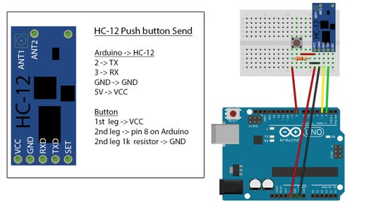
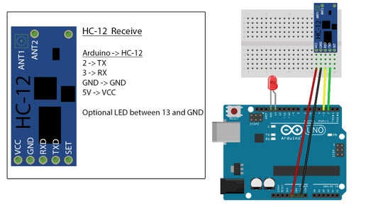
We will use 2 Arduinos with a HC-12 module connected to each of them as you can see in the image.
For both Arduinos we connect pin 2 to TX and pin 3 to RX. Ground to ground and VCC to 5v.
At one Arduino we will add a push button as you can see in the image.
To work with 2 Arduinos on 1 computer, we have to open 2 instances of the Arduino IDE. This means that we have to open the Arduino software 2 times. This is not the same as “file → New”
Save the one with the push button connected as “HC-12 sender” and the other as “HC-12 receiver”.
Make sure that the right ports are selected for each of the Arduinos.
Step 3: Instant Wireless Messenger, Toggle Button, Momentary Button and a Few Useful Functions

Wireless Messenger
We will start by making an instant wireless messenger.
Copy the content from the file “HC-12 messenger send/receive.txt” in the ZIP archive and paste it to each of the Arduino instances. The code is the same for both Arduinos.
After uploading the code, open the serial monitor for both instances.
Now start typing in both serial monitors to start a chat.
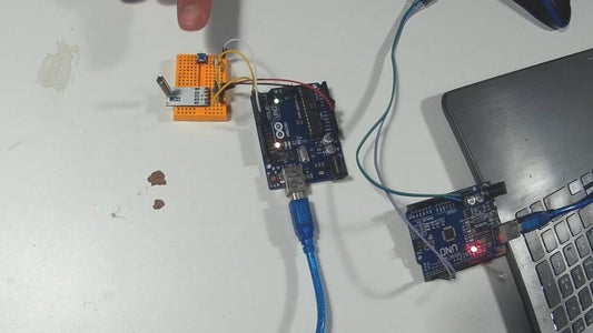
Even your Arduinos are connected to the same computer, the communication is wireless.
Toggle Button
A toggle button is used often in electronics. The principle is very simple. You press a button once to turn on the LED and press the same button again to turn of the LED.
Copy and paste the content of the “HC-12 Toggle Button Send.txt” to the “HC-12 sender” instance and the the “HC-12 Toggle Button Receive.txt” to the “HC-12 receiver” instance and upload.
When you push the button, you should see the LED light up. When you push the button again, the LED turns off.
A few validators like timing and button code are used in order to make sure this example works perfect.
Momentary Button
A momentary button is pretty straightforward. While pushing the button, the LED lights up. When releasing the button, the LED turns off.
Copy and paste the content of the “HC-12 Momentary Button Send.txt” to the “HC-12 sender” instance and the the “HC-12 Momentary Button Receive.txt” to the “HC-12 receiver” instance and upload.
Some useful functions and operators
There are a few useful functions and operators that come in handy when you want to convert or spit a string and convert it to a decimal and so on.
Look at the file “HC-12 Useful Functions and Operators Send.txt” and “ HC-12 Useful Functions and Operators Receive.txt”.
The send sketch sends the string “test123” on button press.
The receive sketch reads the string, split it and convert it to an integer.
Step 4: Advanced Setup. Changing the HC-12 Settings With AT Commands


You can easily skip this section as it will cover some advanced chip settings. However I will cover the basics so you will be able to change the module's baud rate, transmission power, channels and working modes.
A full manual can be found in the ZIP archive under the name HC-12 User Manual.pdf
Connect the HC-12 as shown in the image and connect the Arduino to your computer.
Copy and paste the contents of the file named “HC-12 AT Commander.txt” from the ZIP archive and upload to your Arduino.
Open the serial monitor and type “AT”. If the module returns “OK”, the command mode is working.
Changing the baud rate
Type “AT+Bxxxx”.
The baud rate can be set to 1200bps, 2400bps,
4800bps, 9600bps, 19,200bps, 38,400bps, 57,600bps, or 115,200bps. The default
value is 9600bps.
Example: type “AT+B4800”. The module returns “OK+B4800”.
Changing the communication channel
Type “AT+Cxxx”.
The value can be a number from 001 to 127.
Every number is a 400KHz step. The working frequency of channel 100 is 473.0MHz.
Example: type “AT+C021”. The module returns “OK+C021”.
The module is now set to a working frequency of 441.4MHx
Note that both sending and receiving modules need to have the same frequency to communicate.
Changing the working mode of the module.
This can be FU1, FU2, FU4 or FU4 (FU4 at a baud rate of 1200 sets the chip to transmit up to 1800 meter in open air). See documentation for a full explanation.
Example: Type “AT+FU4”. The module returns “OK+FU4”.
Obtain all parameters from the module.
Type “AT+RX”.
The module should return something like this:
“OK+FU3
OK+B9600
OK+C001
OK+RP:+20dBm”.
More settings can be found in the “HC-12 User Manual.pdf” in the ZIP archive.
Step 5: Spring Antenna or SMA Antenna


The HC-12 modules come standard with a spring antenna. However you can connect an SMA antenna to the board.
There are whole books written about antennas and how they work. I don't want to go to deep into this subject.
The only thing to remember for now is that electronic circuitry can interfere with an antenna and therefore the HC-12 has a IPEX RF socket so you can separate the antenna from the board. This can help for better reception and transmission.
What you need is a IPEX to SMA extension cord and an SMA antenna.
I got my extension here and the antenna here.(check for male and female).
Make sure when you order that the male and female connections match.
You can push the cord on the IPEX connector and solder it on. On the other site of the cord you can screw on the SMA antenna.
Step 6: Final Note:
In this instructable you have learned how to use the HC-12 for long distance communications between Arduinos. You have learned how to make an instant messenger, a toggle button, a momentary button, how to use some string operators and functions, how to change the HC-12 settings and how to use a different antenna.
The making of this instructable took about 100 hours of research, editing, testing, writing and so on.
If this instructable was helpful for you, please click the favorite button and subscribe.
See you in the next instructable.
Other instructables you might like:
$2 Arduino. The ATMEGA328 as a stand-alone. Easy, cheap and very small. A complete guide.
How to fix bad Chinese Arduino clones
Facebook: https://www.facebook.com/OfficialTomHeylen
Donate to help me keep doing this work: https://www.paypal.me/TomHeylen/2usd


