

Introduction: Loud Objects Noise Toy (AKA the Arduino Noise Machine)


I love synths and so, I built this. There are three things that can catch my attention: Synthesizers, Amplifiers and free. The other day (Actually it was just Thursday) I was cruising around Make's website when I saw the Deal of the Day was the Loud Objects Noise Toy. I had seen it before but had not cared much for it. I the n saw a Vimeo video on it and was hooked. I quickly ordered it at half-price from Make but I couldn't wait. I saw the had code on the bottom and so, even though I know it wouldn't work, I tried to compile it. IT WORKED! I grabbed my AtTiny Programming Shield and hit Upload. The results were not satisfactory. Then I said to myself: "If it can compile in the Arduino IDE why can't it Upload?" I uploaded the code and tried every Digital Out pin I could find. I finally reached Pins 10 and 11 and had thought that maybe the code worked but the software didn't. I had tried 9 already and knew it outputted on two pins and the only two pins that were PWM pins were 10 and 11. I tried them and it worked!
Here is the result. The names of the codes were kind of misleading so I renamed them but renamed them as .pde files.
If you have Windows or Mac, use Word to open the code. :-)
P.S. You may be wondering why I haven't posted much lately...midterms. :-)
P.P.S. Second picture goes through every part of Arduino plus the shield.
Step 1: Parts to Acquire.
Bunches of jumper wires.
1 Breadboard
1 Perf board
1 3.5mm female jack (Only if your amp has a male jack. :-))
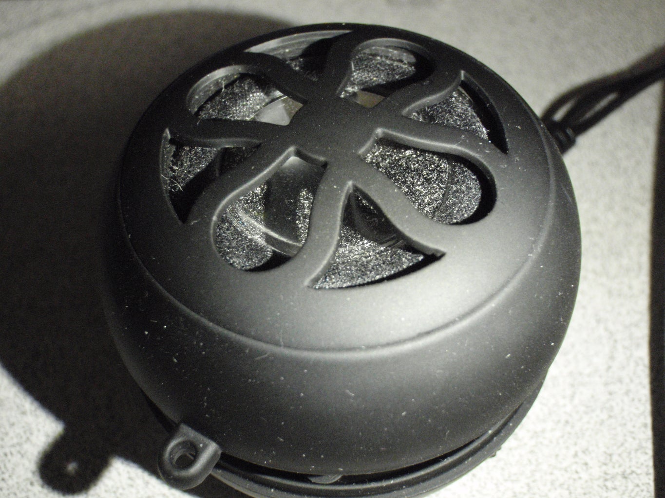
1 speaker with or without an amp (8ohm, 0.25 watts...you get the idea.)
Male Headers (One row of them will do just fine.)
1 Arduino (Preferably UNO.)
Step 2: MUST ATTACH WIRES...MUST ATTACH WIRES...MUST ATTACH WIRES!


I have included a EagleCAD schematic above. REMEMBER IT IS VERY BASIC AND SO, DON'T NECCESSARILY TRY TO FOLLOW THE SCHEMATIC. I will move into Fritzing later on and will add results.
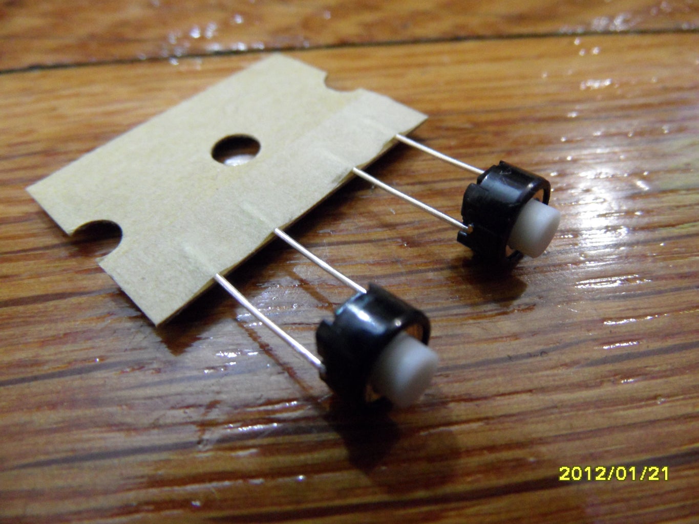
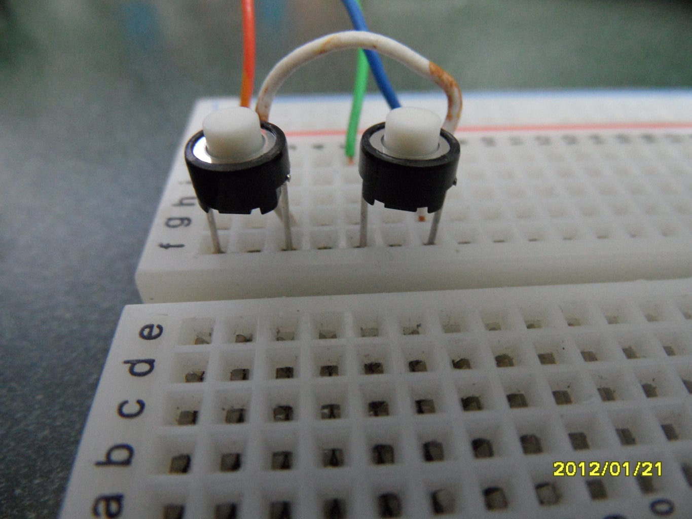
Connect one switch's lead to ground on the Arduino. The other goes to Digital I/O Pin 8.
Do the same for the other except for using Digital 9 for the second switch.
Attach the Jack as shown. If you are using an 8ohm speaker, one wire to either 10 or 11 and the other to ground. Connect it to Pin 11 and Pin 12 for higher sound output...
Attachments

Step 3: Test Your Lovely Circuit.

Plug in your Arduino. Open the IDE. Download the code from below. (Pick RandomBlipsAndBleeps_Metroid. (You can thank me later.)) Upload the code and listen.
If you have Windows or Mac, use Word to open the code.
Here is the code in which you can try in alphabetical order:
Attachments
Step 4: Solder.

Cut the Perf board until it feels most "comfortable" as a shield. You can use my shape if you want. Make sure it doesn't block the valuable reset button unless it is UNO Version R3...
Then solder from the schematic. Remember. Pin 11 not 10 for highest Ouput Level.
One Lead from switch One goes to Pin 9. On the other switch, connect Lead 1 to Pin 8. Both switch's pin 2s go to Pin 13 on Arduino. (AKA Ground.)
Step 5: Fin.
You have now completed your synth. With all these random blips and bloops You could dominate the world...or neighborhood.
This is small, compact and easy to play because you only need two buttons and a speaker.

Participated in the
Toy Challenge 2

Participated in the
Arduino Challenge

Participated in the
ShopBot Challenge


