

Introduction: Low Budget Knife-maker's Bench Grinder


I've been knife-making for quite a few years, and have always relied on a 1"x24" belt grinder, as well as my 4"x36" bench sander to get the job done. For the longest time, I've wanted to invest in a 2" belt grinder, to make the process easier, but could never justify the massive expense that goes into one. That's when I decided to build one for myself.
Problems;
There were three hurdles that I needed to overcome; The first one, was the lack of a local supplier of 2" belts, with the only place to acquire them being online. This was unacceptable for me as there's no bigger frustration than wearing out a belt, finding out you don't have a spare and waiting a week or two for replacements to arrive. The second hurdle was the pulley wheels. I searched everywhere, but couldn't find suitable 2" wheels that would do the job, and especially not in the sizes I wanted. Third, was the motor. It takes a fairly decent sized motor to run a belt sander and I didn't want to spend any more money, than necessary on this project, so recycling was my best option.
Solutions;
The first belt problem had an easy answer; Since 4"x36" belt are readily available at any hardware store, and are rather cheap, I could cut them in half, getting two 2" belts out of each. This would limit the size of the belt sander, but because of the cost effectiveness of this plan, it made perfect sense. The second issue, of the wheels was easily addressed with my lathe. There's a fantastic youtube 'guru' named Matthias Wandel who's used a lathe to create stepped V-groove belt pulleys, and I realized I could do the same for the pulleys on my grinder. If you haven't checked out Matthias' work before, you should. He's a fantastic craftsman. Finally, the motor was a bit tricky. I had a few laying around, but had to rule them out for various reasons. I finally settled on an old tile cutter I had laying around with a 6 amp motor. Now admittedly, I knew it'd be a bit underpowered, but this was an experiment, and if the proof of concept worked, I could upgrade the motor later on. In actuality, the motor ended up working well for lite duty grinding, but if you want to do more intense work, I'd suggest 12A minimum.
In all it was a fun experiment that worked out well, and I thought it was worth sharing with those that would like to upgrade their knife-making equipment but not break the bank doing it.
Step 1: Tools and Supplies


Tools;
- Angle Grinder w/cutoff wheels
- Drill and bits
- 7/16", 1/2" and 3/4" sockets and/or wrenches
- Wood Lathe
- Bench Vise
Supplies;
- Electric motor (min 6A, or 12A recommended)
- Various bearings, 3/4" I.D.
- Nuts, bolts, washers, nuts, lock washers 7/16" and 1/2" in 1", 2", 3" lengths
- 3/4"x4" bolt, washers, nuts, lock washers
- Angle Iron
- 4"x36" sanding belt
- 2" Pulleys
- Heavy Spring
- 1.5"x8" steel flat bar
- 1"x4"x4" blocks hardwood or MDF
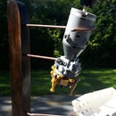
Step 2: The Motor


I had several motors on hand, but the enclosure of the tile cutter made it very appealing for this project. This started off as a bit of an experiment as I wasn't sure if the motor would be strong enough, so I designed it to be modular, with the frame for the belt assembly as a single unit that could be easily removed and reinstalled on another power plant. The speed of the tile cutter motor was perfect for my needs, but I was concerned that its 6A size may be too weak. After some testing, I found that it was just enough for light duty grinding, but deep grinding work would need more power, so keep that in mind when deciding how to power your bench grinder.
As I mentioned, the enclosure for the motor was appealing as it allowed me to create a completely self contained, bench top grinder that could be moved without much effort.
The first step is to strip it down, removing the deck, blade, guard, pan and water catcher, leaving the bare unit. The unit, I used, had a 1/2" lip that overhung the mandrel on the motor which I sliced off using my angle grinder with cutoff wheel. Another advantage, of using this motor, is that it has a threaded mandrel, with a nut that is used to hold the blade, allowing you to install a pully without using a keyway (I'll explain what a keyway is later).
As the pulley I had was too wide for the mandrel, I decided to use the large beveled washers, that normally hold the blade in place, and inverted them to make a V groove. I found it was a bit narrow, so I used a lock washer between to widen the groove. The advantage of doing it this way is that one of the beveled washers has a flat edge, that locks onto a flat edge on the mandrel preventing the pulley from slipping.
The Belt
For the belt, I used a spare 1/4"x20" belt that I had laying around as a spare for my lathe. You can easily use a standard 1/2" belt, but the smaller size is less stiff, putting less pressure on the motor, meaning it doesn't have to work as hard to turn the grinder.
Step 3: Design

The design is simple; A motor drives a belt via pulleys turning a 'master' 4"x2" pulley wheel that the grinding belt wraps around. A second 3"x2" pulley wheel, on bearings, is mounted on a 16" tower set above and 6" back from the master pulley. A third 3"x2" pulley wheel is mounted on a pivot bar, attached half way acting as a tension wheel, draw the grinding belt tight and setting its tracking. The pivot bar is attached to the frame via a strong spring on its opposite end.
Motor mount or Pulley and Belt;
The biggest decision is whether to mount the master pulley wheel directly on the motor, or to use pulleys and a belt to drive it. First and foremost, I opted for belt drive because I wanted the option of switching out the motor to a much stronger one, however I had an alternate reason. When performing intense grinding on metal, there is always the risk of snags and catches. With that in mind, a belt allows for some slippage whereas a direct drive system is less forgiving. It amounts to somewhat of a safety issue during use.
Step 4: Framing and Structural


It's important to note that if you opt to use angle iron, as I did, that it has some advantages and disadvantages. The obvious advantage is that it assembles like the Erector set toys many of us have used as kids. The biggest disadvantage is that it is only strong in two directions, but suffers weakness when twisted. This means that you need to assess how much torque is being applied to the frame by the pulleys and compensate by adding structural support.
Cutting;
You can use a hacksaw to cut the frame, but a good angle grinder with a .45 cutoff wheel will slice through it like butter. After you cut your sections, I recommend de-burring the edges using a wire wheel to prevent cutting yourself during construction. Holes that don't line up can be drilled out using a regular drill bit and some lubricant/coolant.
Step 5: The Master Pulley Wheel


The master wheel is the most important part of the project, as it receives power from the motor and transfers it to the belt. I recycled an old bushing style bench grinder for my project, but I highly recommend using bearings instead. Bushings do work, but they heat up, and require regular greasing. More than that, they throw grease, which can be rather annoying as you're working.
The Shaft;
There are two ends to the shaft, each using an opposite thread so that, as the grinder rotates, it doesn't spin its wheels off. If you salvage one, as I did, make sure you save the end with the counter clockwise thread, otherwise you'll need to make a crown bolt (I'll describe how to make one later) and a cotter pin. This will be the end that you'll mount the master pulley wheel onto.
The belt pulley;
Keeping with the theme of recycling, I recovered an old pulley from another project. Unfortunately, I'd cut the piece for the grub screw that would normally be used to mount it, but that wasn't a real problem. Using two lock rings, that were a part of the old bench grinder, I created a 'keyway' that would lock the pulley in place by grinding down a scrap of steel into a square 'key'. I then used my angle grinder and created a channel in the end of the rod. Slid between the pulley, and the slot in the rod, the keyway would effectively lock the pulley into place, preventing slippage.
Step 6: Creating the Pulley Wheels


I created my pulley wheels using some scrap 1" hardwood I had laying around but it can, just as, easily be done with MDF, plywood or other construction grade material. Be sure to stagger the grains of your slabs as it will add strength to the wheel, preventing them from splitting.
There are three wheels you'll need to make; The master, the top wheel, and the tension pulley. The master is made of two 5x5" pieces of 1" wood, while the top and tension wheels are made of 4"x4" pieces.
Process;
Start by gluing two 1"x5", two 1"x4" and two 1"x4" pieces together, and clamp tightly. Once the glue has dried, cut the corners off using a chop saw, then find the center of each piece. Set them in your lathe, reducing their diameter until you're left with a 2"x4" wheel, and two 2"x3" wheels.
The Top and Tension Wheels;
Next, you have to set your bearings on 2"x3" wheels. Choose a forstner or spade bit, and using the center you set on your lathe, drill to the depth of your bearing. The inner core of your bearing will need to spin freely, so you'll need to drill through the wheels to the width of the inner ring. This will allow the bolt to pass through, and not have the bearing seize up against the wheel.
The Master Wheel;
This one is done a bit differently. There are no bearings, however if your shaft end is shorter than the 2" width, you'll need to recess the wheel to get it to fit properly. Measure the diameter of your shaft, and drill out the center of the wheel to fit. Try and keep your tolerances tight as any play will cause wobbling.
Bolting Through The Wheels;
Since you're counter sinking the wheels, you should bolt the two halves together and not rely solely on the glue Remember to countersink the heads of the bolts that will be riding closest to the frame as you don't want them to make contact.
Step 7: The Tension Arm


The tension arm is cut from a scrap piece of 3/8'x1.25" bar stock to 8" long and its ends are rounded over. You'll need to drill some large holes in it, so I recommend using a drill press, and a lot of WD40. You'll need 4 holes; a center hole that will act as a pivot. This hole is slightly off center and is set 3" from one end. A second hole is at the end closest to the pivot which will be used for attaching the spring. Two additional holes need to be drilled at the opposite end, roughly 2" apart. These should be larger as they will act as the tracking adjustment which I will outline later in the instructable. Once you holes are drilled out, and the burrs removed, you can mount the tension arm on the vertical beam between the top wheel and the deck of the grinder, with the spring end forward toward the master wheel. It will need to move freely, so I recommend double nutting it and leaving some play so that it can move without binding.
Step 8: Setting Your Wheels


The top wheel is static, and needs to line up perfectly with the tension wheel and the master wheel. You can rough them into place, but I recommend checking their set as you go. You can add spacers by using washers, or if more space is needed, extra nuts between the frame and the wheel.
Don't install the tension wheel permanently just yet. We need to create the tracking adjustment.
Step 9: The Tracking Adjustment


Wear on the wheels, or imperfections in the belt can cause it to ride one way or the other as it spins. The tracking adjustment is an assembly on the tension wheel that allows it to be angled so that the grinding belt can be centered by forcing it in either direction allowing for these imperfections. It's construction is much simpler than it looks and consists of a set bolt, a loose tension wheel, and an adjustment bolt.
Drilling Holes in Bolts;
To drill the necessary holes in the bolts, I created a jig with a v-groove in it that is used to support the bolt, preventing the drill bit from gliding. You can do this freehand, but I wouldn't recommend it.
The Set Bolt;
The set bolt is simply a bolt with a hole drilled through it that is set into the tension arm, in the hole that is closest to the pivot point. Because its head sits between the wheel and the arm, you'll either need to countersink it, or thin it so that there is enough room for the wheel to spin unhindered. The bolt should be set into the tension arm as you see it in the third image.
The Wheel Bolt;
The tension wheel is set loosely into the tension arm so that there is some play in it. This means that it cannot be bolted tightly to the arm itself, necessitating the creation of a 'crown' nut. A crown nut is just that, in that notches are cut into it so that it resembles a crown. The bolt itself will have two holes drilled into it; one for the adjustment bolt that will line up with the hole in the set bolt, and one for the cotter pin that will be used in conjunction with the crown bolt.
The Tracking Bolt;
Once your tension wheel is set onto the arm, you can install the tension bolt which will pass through the holes in both the wheel bolt and the set bolt. It works by pulling the wheel bolt inward, which angles the tension wheel outward, forcing the belt to track inward toward the unit. The spring on the opposite end of the tension arm acts as the tracking in the opposite direction. I recommend double nutting the tension bolt or using nylock nuts as vibration from the unit will invariably mess with your tracking setting.
Note: You can add a spring behind the tension wheel, which will stabilize it, but I didn't and haven't found that it makes any difference. It's your choice to do so, as the advantage is it will limit some of the extra play in the wheel, but again, I didn't add one without problems.
Step 10: Finalizing the Tracking and Tension


When all is said and done, you'll need to go over it again and ensure the tension, and tracking are all correct. This means you get to turn on the assembly for the first time, which can be pretty scary, as it's kind of like driving a car where the steering and drivetrain are all out of wack. I suggest quick on/off toggles on the power supply as you adjust, and not turning it on fully until you get it dialed in correctly.
The trickiest part, for me was actually setting the spring. Too tight, and the belt won't spin well...too lose and it will not be able to track, and even fly off which can be dangerous.
Step 11: Finished


That's it. It'll take some tweaking and tuning, but you should end up with a decent light duty grinder that can be upgraded for heavy duty work.
As usual, I hope you enjoyed the instructable and thanks for following.

Grand Prize in the
Trash to Treasure Challenge

Runner Up in the
Metal Contest 2016


