

Introduction: Low Cost LED Grid

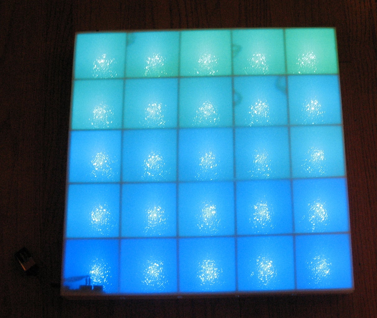
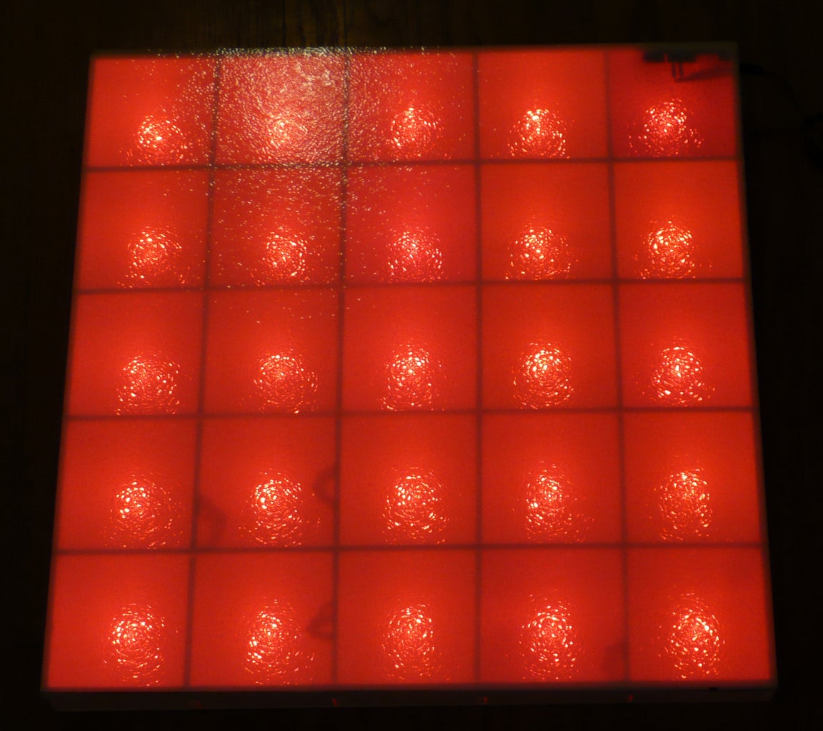
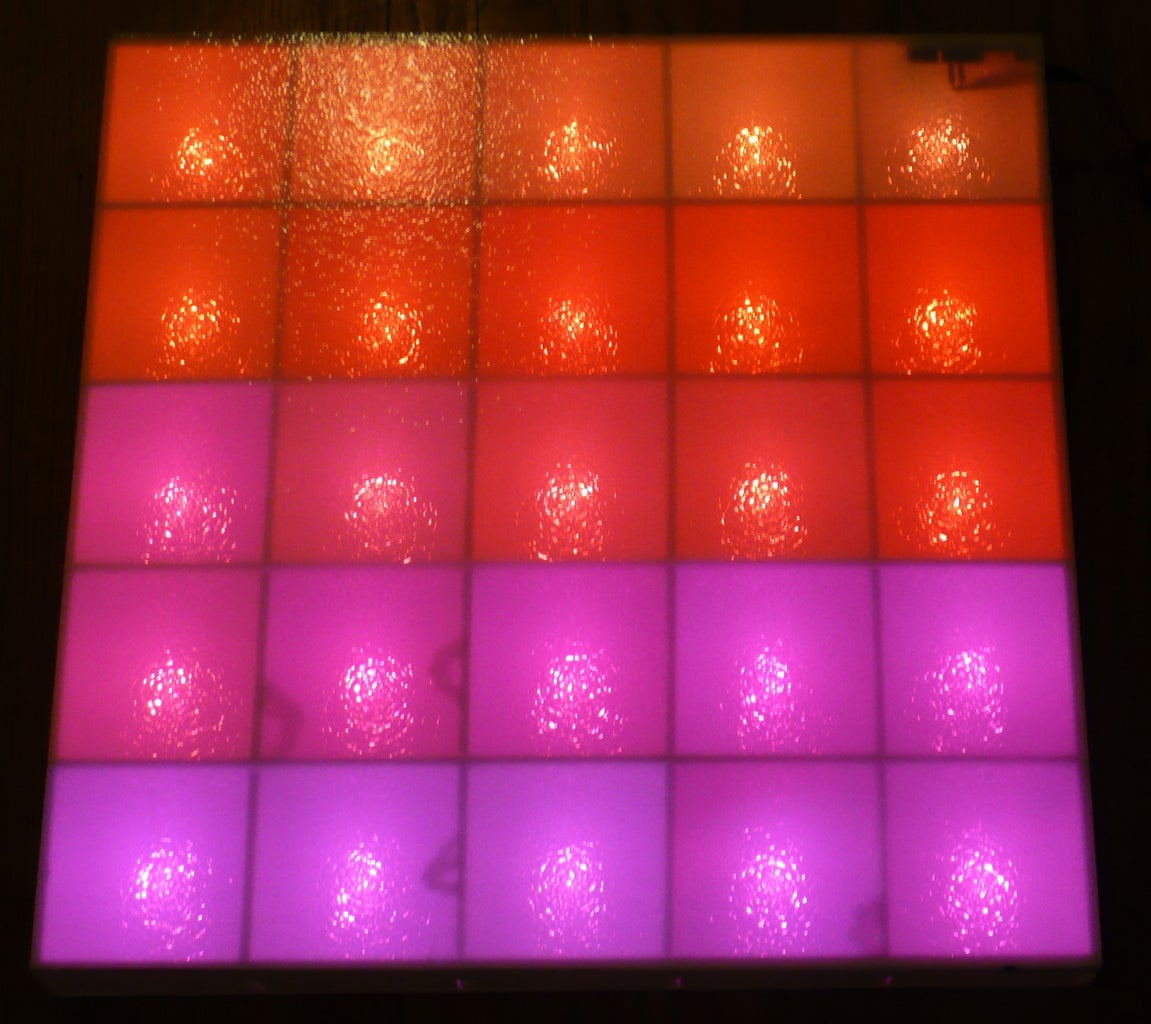


This project uses a couple of sheets of foam core, a fluorescent fixture cover from the local home store, a cut up strip of WS2812b LEDs, and an Arduino. All fairly inexpensive if you know where to get them (info below).
Parts:
- LEDs - this project uses 25 LEDs, and there are a few choices here. For this one, a strip of WS2812b LEDs was used. There were 30 per meter in the strip I ordered, which makes soldering easier since they are farther apart. The 60/meter strips would also work. The 144/meter would not work since they only have one set of solder pads between each LED to allow them to be so close, and for this project, we are soldering wires between them all and need soldering pads on both sides. You could also use the WS2801 based strands, and those are typically pre-wired, making the project even easier. The other Instructables cover those pretty well, so this one will not go into more detail on those. Use non-waterproof or silicone jacketed (the jacket can be slid or cut off) strips. Avoid the epoxy waterproofed ones since you will need to clean that off of each end of each LED - doable, but unnecessary work if you order the other kind.
- Foam Core - 2 sheets, 20"x30", like these, though that link is 5x more than you need.
- Plastic cover - this is from the local home store and is used to cover fluorescent bulb fixtures. It's called an acrylic lighting panel, and the style is cracked ice. There are other possibilities here - the main thing is there is enough frosting to diffuse the LED light. Since the lighting panels are about 24"x 48", you can make two of these projects with one of them.
- Wire - each LED will have wires to connect to the next one - three wires between each. Hobby servo wire is nice to use since it's already three wires and color coded nicely.
- An Arduino Uno will do. Clone Arduinos are are available for about $10 each - a key for the low cost goal of this project. There are also smaller versions of Arduinos that would also work well for this project in that same price range. Older Arduinos will work fine too.
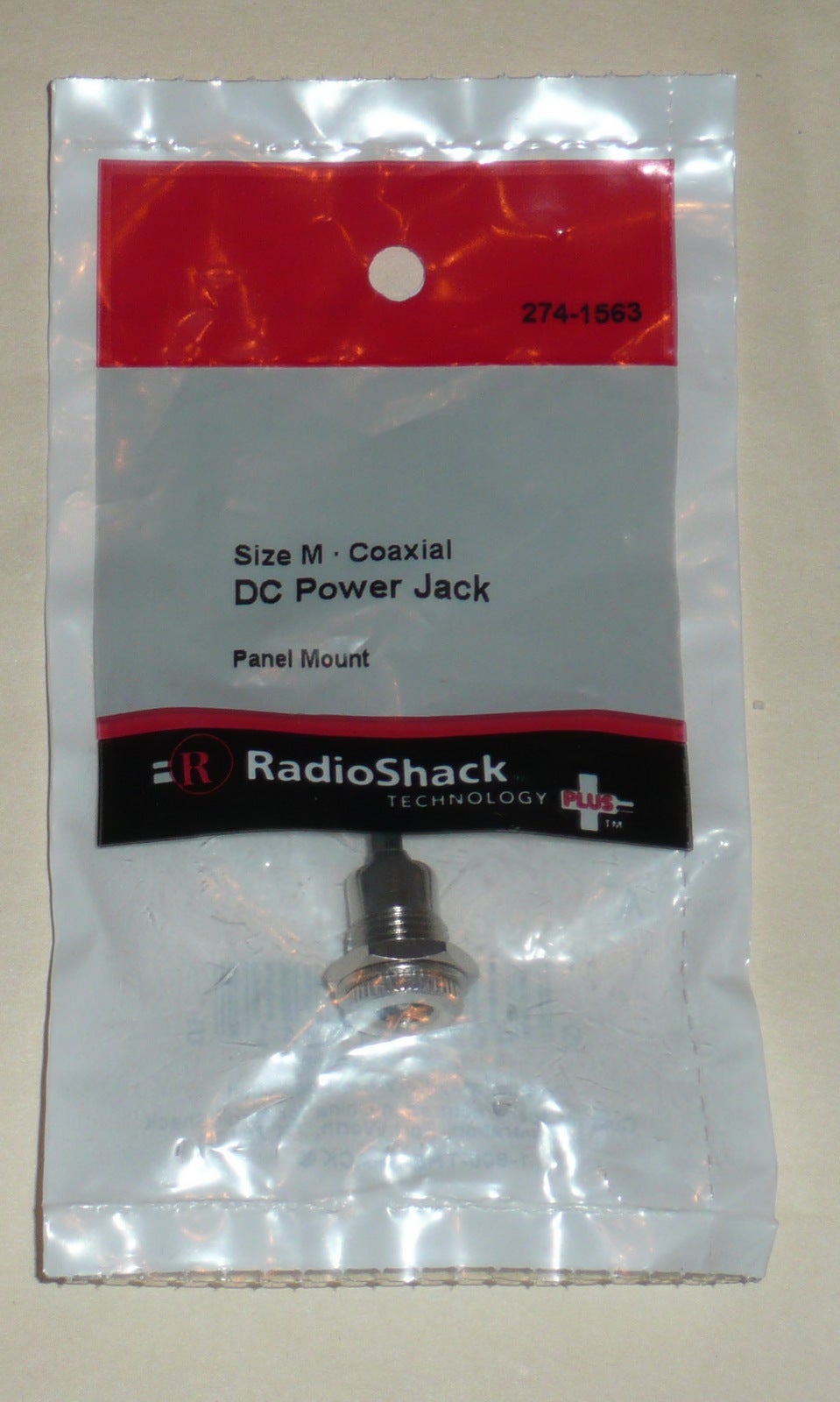
- Recommended - a power jack to supply 5 volts to the system. You can use the Arduino power and regulator if most of the LEDs are not on at the same time, but if they will all be on, the external 5 volts supply will avoid overheating the Arduino regulator. This jac will match your power supply - for me, it was a 2.1mm ID, 5.5 mm OD panel mount jack.
Step 1: Making the Grid


Cut (12) 2" strips off the 20" end of one piece of foam core. Cut the second piece of foam core into a 20"x20" piece for the back.
On the strips, cut a 1/4" wide, 1" + 1/16" deep slot on the end, and at 4", 8", 12", and 16" (see the pictures). They are all cut the same and will fit into each other. This is easy if you have a band saw, but you can use a hand saw or an X-Acto knife and some patience.
On 4 of them, cut a notch on the tops to run the wires. On 4 others, cut notches on the bottom left of two of them and the bottom right of the other two. The remaining 4 are the sides and need no notches (the pictures show each of the 4 types).
Don't glue them all down yet since you will need to run the wires! I used hot melt glue. I glued the sides in first - added the strips in the one direction that is captured by the sides, but did not glue them yet. Then I noticed you can remove them by flexing them slightly, and removed them while gluing down the LEDs. Once all the LEDS are set, you can add glue as needed, but you may not actually need much more - depends how rigid you want it to be.
Cut the plastic lighting panel to 20"x20". It is very brittle, so the special scoring tool they sell may help - otherwise a box cutter may work, but be sure to have the panel on a flat surface.
Step 2: Soldering the LEDs


If you have a string of the WS2801 + LEDs that are pre-wired, then this is an easy step. You can either glue them in each box, or drill holes and mount them from underneath. Putting them inside the box makes the back of the panel much cleaner since the wires will be hidden.
For the WS2811 or WS2812 LED modules, you can solder them together with a little time. The soldering pads on the LED strips are far enough apart that they are easy to solder. Cut apart 25 LEDs from the strand.
Cut (25) 5 inch lengths of the 3 conductor servo wire. Start by soldering the three proto-board jumpers to the first wire and use heat shrink tubing to cover those connections. Note: If you will have a separate 5v power jack (recommended - see power note below), add another wire to these connections. So, for the +5, you will have the jumper wire to the Arduino, the servo wire to the first LED, and the power wire to the power jack. Same for the Gnd. Soldering the wires to the power jack will need to be done after you mount the jac, and you can use some heat shrink tubing on those connections as well.
Then solder the first LED on the other end of that first wire. It's easiest to pre-tin the wires and the LED soldering pads. Note that the LEDs have a direction for passing the data, so make sure the arrows are pointing away from the Arduino.
If you setup the Arduino ahead of time, (see that step ahead) you can test each LED as you go to make sure the string is working.
Once you have them all soldered and tested, you can hot melt glue them into the boxes. See the pictures. Some of the wires may stick up and cast a shadow - these can be glued down as necessary.
A note on power: We have 25 LEDs x 60ma per LED = 1.5 amps max if they are all on full (white). This is beyond the limit of the voltage regulator for the Arduino, which is about 1 amp. But, normally, they are at different colors and brightness levels, so it should be OK. But, I wrote a program to show random colors, and since they were all on, the Arduino regulator started overheating, so a separate 5v supply for the LEDs and Arduino is recommended. The nice thing about adding this jack is that it is easy, and you can then power the panel from any of the ports - USB, The Arduino power jack, or the 5v jack - all three will power the LEDs and Arduino.
To use a 5 volt supply, you will need a panel mount jack that matches the wall adapter. A 5 volt, 2 amp or greater wall adapter should work fine. They usually come with 2.1mm or 2.5mm inside and 5.5 mm outside dimensions. Once you add the jack to the box, you just need to connect those wires to the existing +5 and Gnd wires (per above).
The Arduino was placed against the wall of the first compartment and holes cut for the power and USB connections. This does show up a bit, though less so in person that in the pictures.
In the spirit of keeping the cost low, I simply used transparent tape to hold the top on. Pairs of magnets might be good too.
Step 3: Programming the Arduino
There are several Arduino Libraries available to work with these LEDs. Adafruit has some good ones - one for the WS2801 strings, and one for the WS2811/WS2812 LEDs, which they call "Neopixels".
Once you have the LED library, the coding is fairly easy - you can set the color for any particular LED, and use the show command to send the pixel commands out to the string. The Library has a sample program that works nicely on this panel.
The Arduino can actually handle many more LEDs, so if you build several of them or a larger one, you can connect the data wires together. With more LEDs, though, you would definitely want to go to a separate 5v power source that can supply more current.
You could also add a push button to switch between animations.
There are many ways to improve this project, and hopefully it gives you some ideas for a cool project to build! Share your cool animations!

Participated in the
Manly Crafts Contest

Participated in the
Make It Glow Contest


