

Introduction: Low-Cost Linear Actuator Based on the Sarrus Linkage


Linear actuators are used in all sorts of cool machines such as 3D printers, laser cutters, and CNC routers. One of the main contributors to the total cost of these devices is the linear guideway, which consists of components that maintain the straight-line path of the actuated portion of the device (e.g. a set of precision rods and linear bearings). Prices for guideway components can range from tens to thousands of dollars depending on their size and accuracy. One way to get around the high cost of these components is to replace them with a mechanism that converts rotary motion into straight-line motion. The Sarrus linkage, invented in 1853 by Pierre Frédéric Sarrus, is one such mechanism that can produce perfect straight-line linear motion without the use of any reference guideways. This project utilizes simple 3D printed or laser cut linkage plates and plastic "living" hinges to construct a low-cost Sarrus mechanism. A NEMA 17 stepper motor and threaded rod are then added to get it moving. The travel length of the actuator in this project is approximately 10 inches (254 mm) but larger or smaller version can be made by simply changing the length of the linkage plates. Enjoy!
Step 1: Materials and Tools


Materials
A. Linkage plate (4 each, 3D printed or laser cut in Step 2)
B. Motor plate (1 each, 3D printed or laser cut in Step 2)
C. Actuator plate (1 each, 3D printed or laser cut in Step 2)
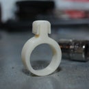
D. Plastic hinge (6 each, McMaster-Carr part no. 1637A713)
E. Flat head screw, 6-32 thread x 3/8 in. long (24 each)
F. Press-in nut, 6-32 thread (1 pack of 25, McMaster-Carr part no. 94674A515)
G. Socket head cap screw, M3x0.5 x 12 mm long (2 each)
H. Hex nut, M3x0.5 (2 each)
I. Socket head cap screw, M3x0.5 x 10 mm long (4 each)
J. Shaft coupling, 5 mm to 8 mm (1 each)
K. NEMA 17 stepper motor with M3x0.5 threaded mounting holes (1 each)
L. M8 Acme threaded nut (1 each)
M. M8 Acme threaded rod, 300 mm long (1 each)
Tools
N. Metric hex key set
O. #2 Phillips head screwdriver
P. Needle nose pliers
Step 2: 3D Print or Laser Cut the Sarrus Linkage Plates
Using the attached STL or DXF files, 3D print or laser cut the following parts:
- Linkage plate (4 each)
- Motor plate (1 each)
- Actuator plate (1 each)
The parts used for these instructions were 3D printed in gray ABS plastic. If you laser cut your parts, the thickness of the material should be around 0.25 in. (6.35 mm) thick. Wood, acrylic, MDF, or any other rigid material should work fine.
STEP files have also been attached for anyone who wants to make modifications prior to printing or cutting. If you're planning on using this actuator in an actual machine, you will probably need to add some custom mounting holes and/or increase/decrease the length of the linkage plates to fit your application.


Step 3: Insert Press-Fit Nuts


Insert press-fit nuts into the linkage plates, motor plate, and actuator plate as shown. Pay careful attention to the orientation of the motor plate and actuator plate.
Step 4: Install Linkage Plate Hinges


Position a plastic hinge between two linkage plates as shown and secure it using four flat head screws. Be careful not to over tighten the screws.
Repeat this step and connect the two remaining linkage plates with a hinge. You should have two sets of hinged linkage plates at the end of this step.
Step 5: Install Motor Plate Hinges


Position the motor plate and the two sets of linkage plates as shown. Install two plastic hinges between the motor plate and linkage plates using eight flat head screws.
Step 6: Install Actuator Plate Hinges


Position the actuator plate and linkage plate assembly as shown. Install two plastic hinges between the actuator plate and the linkage plates using eight flat head screws.
Step 7: Install Acme Nut


Insert two M3 x 12 mm socket head cap screws through the actuator plate as shown. Slide the Acme nut down onto the screws. Thread two M3 hex nuts onto the ends of the screws. Flip the actuator plate over. Tighten the two screws by holding the nuts with the needle nose pliers (or a wrench if you have one) and turning the screw with the appropriate size hex key.
Step 8: Attach Stepper Motor


Attach the stepper motor to the motor plate using four M3 x 10 mm socket head screws.
Step 9: Attach Shaft Coupling

Insert the 5 mm diameter end of the shaft coupling onto the stepper motor shaft. Tighten the set screws using a hex key (key size may vary depending on where you purchase the coupling from).
Step 10: Install Acme Threaded Rod


Thread the rod through the Acme nut about half way. Flex the Sarrus linkage so that you are able to insert the threaded rod into the shaft coupling. Tighten the set screws on the shaft coupling using the appropriate size hex key.
Step 11: Make Things Move... in a Straight Line


You're done building! Now you'll need to hook up your stepper motor to a controller to make it move. There are lots of great Instructables on how to do this, for example: https://www.instructables.com/id/Controlling-a-Step.... As always, I welcome your comments and feedback (good or bad).
If you like this Instructable, please vote for me in the Epilog VII and Robotics contests. Thanks!

Runner Up in the
Robotics Contest

Participated in the
Epilog Contest VII


