

Introduction: Luxo Maginfying Lamp LED Upgrade


I'm lucky enough to have a father-in-law who was once a dedicated tinkerer like myself. Occasionally, he will bestow upon me one of his prized "old-fashioned" tools. These pass-downs are often antique treasures, that have been loved and appreciated for decades. I think he gives them to me, because he knows that I'll do more then just look at them. This vintage Luxo Magnifier lamp is one such item.
I've enjoy it's retro glow for many years... and often commented that it will be a shame when the bulb finally goes.
Well... that sad day came recently. While moving the lamp... I bumped her a little too hard and shattered the bulb.
(safety note:in addition to potentially sharp glass... fluorescent tubes contain VERY small amount of mercury. They should be handled and disposed of correctly)
I decided to take this opportunity to "fix" the lamp by upgrading it to LEDs (which I happen to have LOADS of.
This will also be another excuse for me to design and print something on my new 3D printer (optional). And I'll be able to use my soldering iron (that I just got for Christmas)... AND I'll be able to get my daughter involved (I think she'll like soldering). And I'll be able to write my FIRST Instructable (something I've been wanting to do for a long long time now). This is like a WIN - WIN - WIN - WIN situation!! Some might think that I broke that bulb on purpose... but it WAS an accident... I swear.
Step 1: Understanding This Upgrade
Since the original lamp is an AC Fluorescent Lamp and what we are aiming for is a DC LED Lamp... there are a few key differences that need to be pointed out:
AC Fluorescent Lamp:
- Uses AC voltage (200-500 volts)
- Requires a ballast transformer to produce an "inductive kick" to ionize gasses inside the bulb
- Ionized gases produce invisible UV light when current flows through them
- A phosphor powder coating converts the UV light to visible light
- Light is diffuse (not-focused)
- Have slight "flicker" due to AC voltage
DC LED Lamp:
- Operates on 12 volts DC
- Needs a AC-DC converter Power Supply
- Produce light based on the type of LEDs used
- LEDs are highly energy efficient, durable, dependable, and cheap
- LED light can be focused or diffuse depending on their design and application
- LEDs powered by DC do not produce "flicker"
The bottom line is this:
We will need to remove the components that make this an AC Fluorescent Lamp (ballast, bulb, and switch) and replace them with components for a DC LED Lamp (AD-DC converter Power Supply, LED light ring, and switch).
Step 2: Gather the Required Tools


Hand Tools:
- screwdriver
- pliers (needle-nose)
- wire cutters
- wire strippers
- file
- hacksaw
Electric Tools:
- soldering iron (and solder)
- cordless drill or electric screwdriver (and bits)
- rotary tool (optional)
- hot glue gun (optional)
- multi-meter (optional)
- 3D printer (optional)
Electronics Accessories and Components:
- 15 - Ultra-Brite White LEDs
- 5 - 220 ohm resistors
- perf-board (small scrap piece)
- power switch*
- 12VDC wall wart
- hook-up wire (22 AWG solid)
- wire nuts
- electrical tape
- heat-shrink tubing
- test leads (one pair)
3D Printed Parts: (optional** - downloads provided)
- light ring
- switch adapter
Fasteners:
- reuse removed bolts, screws, covers, and clips
- some fasteners were replaced with longer alternatives (I will point out again in the associated step)
Note: Most tools and parts were items I had available to me at the time. I used bits and pieces left-over from other projects. You can (of course) modify these instructions based on what YOU have available.
* I DID go to RadioShack for the illuminated power switch... because I didn't like the spares I had available.
** The 3D printed parts were easy for me to print... but you COULD fabricate something similar out of other material(s) such as wood or plastic and achieve similar results, using standard tools.
Step 3: Remove the Guts


DON'T FORGET TO UNPLUG THE LAMP!!
Disassemble the electrical base and the light ring:
- Remove screws, covers, clips, fasteners, wire-nuts, switches, lens, etc...
- Set aside the stuff that we don't need for right now.
- It's okay to leave the wire threaded through the boom arm... we'll be using THAT later
Step 4: Ensure the Wall Wart Fits Inside the Electrical Base

It's important to make sure, before you go much further, that your 12VDC wall wart will fit inside of the electrical base (where the ballast transformer once was).
Step 5: Remove the Wall Wart Power Supply


Using a hacksaw, rotary tool, and/or files careful cut and pry open the wall wart and remove the circuit board (Power Supply) inside.
Step 6: Desolder the Old - Solder the New


Here we remove the bits of old wire left attached to the circuit board... by desoldering them.
Then, we solder new, longer, color-coded wires on.
For the new wires, I used some of the same stranded wire that was already attached to the lamp. My lamp had plenty extra... so I just trimmed it and re-used it.
I'm assuming that if you have the tools needed and the desire to take on a project like this... that you already understand basic electrical repair techniques such as stripping, tinning, and soldering. So, I won't bore you with a lesson in those things... perhaps in another instructable?
Step 7: Mark the Wires (Both Ends) for DC Polarity


Since we are converting from AC to DC... it is important to note which wires (to the lamp-end) will carry which polarity.
Using a multi-meter you can check continuity to identify the which ends are connected.
Again, using a Sharpie... I marked the ends. Red for positive (+) and Black for negative (-).
Step 8: Install the DC Power Supply


- Now install the DC Power Supply into the lamp's electrical base.
- It helps to reuse the original plastic casing (from the wall wart) to protect the circuit board.
- You can use electrical tape to hold it all together.
- Insert the boom arm (and wires) and fasten it all together with the lock screw
- Connect the wires (as shown).
- Re-install the cover.
Step 9: Just a Quick Test

This is a good time to quickly check to make sure the Power Supply is working and producing some DC voltage at the lamp end.
- Plug it in
- Check for potential (using a multi-meter - DC volts scale)
- Don't Forget - Unplug
Without load (something to power - like LEDs)... don't be surprised if the voltage is higher than expected, this is normal. All we are looking for right now is: "Do I have power... and not sparks or smoke?"
If something goes WRONG - Unplug IMMEDIATELY... and recheck your wiring connections
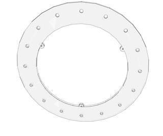
Step 10: Fabricate a Light Ring


I used a 3D Printer to produce my LED light ring.
- If you don't have a 3D printer... that shouldn't stop you from proceeding.
- This ring is NOT complicated.
- It can be made out of whatever you have:
- plastic, plexiglass, plywood, wood veneer, papier-mâché, even cardboard (use your imagination)
- If you DO have a 3D Printer:
- This ring is NOT complicated.
- You could design your own in minutes using TinkerCAD or other 3D Modeling software
- or just download the .stl file (that I've included)
Some notes about MY light ring design:
I added a slight inward angle (10 degrees) to the holes that hold the LEDs... I did this so that the focused LED beams would converge on a point below the magnifier at approximately the ideal viewing distance (the distance below the magnifier that I like to hold objects for optimal, in-focus viewing - about 20 inches).
If you are interested in how I arrived at 10 degrees... I've included a some scribbled trigonometry for your enjoyment.
-------------------------------------------------------------------------------------
If you still want 3D printed parts and don't have a 3D printer. It's possible to have someone print them for you at 3D Hubs. If you want... you can even ask ME to print it for you (search for OneEarWillie on 3D Hubs).
Attachments
Step 11: Some More Maths


Before we start installing LEDs... First, let's do a little basic electrical theory to determine a few things:
- How many LEDs can we power with our Power Supply?
- How do we want them configured?
- What sized current limiting resistor(s) should we use?
How many LEDs can we power with our Power Supply?
- My Power Supply:
- supplies 12VDC
- at up to 1.0 Amp
- My LEDs:
- require about 3.0-3.2 Volts to forward bias
- can handle about 15-18 milliAmps (.015 Amps)
So we'll be able to put up to 3 LEDs in each branch and still get them all to turn on (12V/3V = 4).
Actually, 4 could work... but, once we add a current limiting resistor, there might not be enough voltage left to forward bias all 4... so we'll stick with 3.
With 1.0 Amp of current we could support over 60 branches (1.0A/0.015A = 66.7)... that's more than 180 LEDs (3 * 60 = 180). We don't need THAT many!
How do we want them configured?
Since we don't need 180 <--- Boy-oh-boy, THAT would be BRIGHT!!
How about 15 (5 branches of 3 LEDs)? Sounds good to me.
What sized current limiting resistor(s) should we use?
The current through each branch needs to be less than 15mA. And since LEDs have almost no internal resistance... we'll need to add a current limiting resistor to each branch of LEDs. Otherwise, they will allow too much current flow and the LEDs will burn out. (don't believe me?... try it... you'll see - It'll cost you a few LEDs)
So to figure out the resistance value (per branch):
- Each LED drops 3V (3LEDs * 3V = 9 V)
- Total Voltage = 12V
- Remaining = 3V (12V - 9V = 3V)
- Ohm's Law: I=V/R = 3V/0.015A = 200ohms
So if we use a 220ohm resistor... we'll be safe (no LEDs will be harmed in the making of this lamp).
Step 12: Installing the LEDs


To get even spacing - I used 16 evenly spaced holes... then ignored one of them (for wire routing). This left me with 15 evenly spaced LEDs and one gap.
Here's an easy way to space them:
- I divided the ring in half
- Then in half again... quarters
- Then divide each quarter in half... now you're at 8
- Then divide each eighth in half also... now you have 16 (done)
I marked up my light ring to show the layout... I also noted the orientation of the LEDs to make it easier later.
Note: I swapped the LED orientation (polarity) for 2 of the groups... to make it easier to wire.
- Insert the LEDs with correct orientation.
- Bend the legs so they touch in groups of 3.
- Solder them together.
Tip: Test your LEDs prior to installation... this will save you the trouble of replacing a bad one later.
And easy way to test... is press each LED legs to opposite sides of a 3V button battery (CR2032 or similar). Long leg (anode) goes to the positive side of the battery. If it lights... it's good.
Step 13: Another Quick Test

To make sure everything to configured correctly and that no LEDs were damaged in the soldering process... it's a good idea to give them one more quick test.
LED Group Testing Procedure:
- Attach test leads to the lamp end Power Supply wires (12VDC)
- Plug in the Power Supply
- Attach the neutral lead to the negative (-) end of a group of LEDs
- Clip a 220 ohm resistor in the positive (+) lead
- Touch the free end of the resistor to the positive (+) end the same group of LEDs
- All 3 LEDs in that group should light brightly
- Repeat this test (steps 3 - 6) with the other groups of LEDs
- Unplug the Power Supply
If any of the LEDs fail to light (or are dim)... investigate the problem before continuing
Problems can be caused by:
- Poor connections (solder joints,clips)
- Backwards LEDs (reversed orientation or polarity)
- Damaged LEDs (broken or overheated)
- Incorrect power (wrong polarity or voltage)
- No power (Power Supply problem)
- Incorrect resistor value (incorrect or damaged resistor)
Step 14: Distribute Power to the LED Groups


To create a power distribution network, I used:
- a scrap of perf-board (trimmed and filed smooth)
- 22 AWG Solid wire (cut to length and soldered to the perf-board)
- 5 - 220ohm resistors soldered to the positive ends of each LED group
Steps:
- Solder the power supply wires to the perf-board
- Create a positive header by adding additional wires to the perf-board and joining them together with solder
- Create a negative header by adding additional wires to the perf-board and joining them together with solder
- Position the perf-board with headers on the ring near the unused hole
- Route the Power Supply wires through extra hole
- Trim off excess leads and wire
- Complete the remaining soldered connections
Step 15: One More Test... Then Glue


Once more... let's make sure everything is working like expected before we apply glue.
- Attach test leads to Power Supply wires
- Attach free ends to completed LED light ring wires
- Plug in the lamp
- ALL LEDs should be brightly lit
- Unplug the lamp
If everything works... it's time to glue!
Apply hot glue to the distribution circuit board and various other places hold wires in place.
Step 16: Replace the Switch


The switch that comes with this lamp is specifically designed for starting and operating a fluorescent lamp. It's NOT the ideal switch for turning ON-OFF a DC circuit.
So we'll need to replace it with a simple toggle (SPST) switch.
Although I have a ton of these scavenged from other projects... I wanted something a little fancier for my lamp. So, I picked up a light-up push-button toggle at RadioShack (one of the few that are still open in my area) for a few bucks.
I used the wires from the old switch to wire up the new one. Because it's an illuminated switch, it needs 3 wires. I made the common one black.
I used a Dremel rotary tool (a hand file would also work) to shape the hole to fit my new switch. I also 3D Printed a simple adaptor to make the rectangular hole into a round one. Again... this is completely optional... but looks really nice!
If you're interested... I've included this .stl file also.
Attachments

Step 17: Wiring Up the Light Ring


Depending on the type of switch you are using... how it gets connected might be different.
In my case, I was using a SPST switch... but since it was illuminated, it needed an extra wire, to make its internal light shine.
To help out, I've sketched up a few of the more common types of switches you'll come across. This list is FAR from complete. For more information on switches... there are PAGES of information just a Google away on the internet.
Step 18: Fasten the Light Ring and Mangifier Lens


Since the light ring was about 3mm thick... I needed to use some slightly longer screws to fasten everything together again.
These 3 screws hold both the light ring AND the clips that secure the magnifying lens in place.
Step 19: All Done... Now It's Time to TINKER!


Now you can plug her in and test her out.
I'm pleased with the results. Nice, bright, focused light... right where I need it!
At this point, I'm not sure if I'd change anything. At first glance it seems less bright than before... but I'm not using it to light a room. It is plenty bright under the magnifier... and that's what I was looking for.
---------------------------------------------------------------------------
I hope you enjoyed my first instructable. I look forward to your questions, comments, and feedback.
I think I'll enter this into a contest and see what happens! If you enjoyed this please vote for me.
Happy Tinkering!

Participated in the
Full Spectrum Laser Contest 2016


