

Introduction: MULTIPLEXED LED MATRIX WITH DRIVER CIRCUIT


This is an instructable for constructing a multiplexed 8*8 LED matrix using conventional RGB LEDs.
Multiplexing is done to be able to interface more LEDs with lesser pins of the microcontroller. I have used MSP430G2553 microcontroller to interface the LEDs.
During multiplexing of LEDs we use the concept of persistence of vision. If we turn on and off the LEDs at a frequency of approximately 50Hz and above it appears to be on continuously to the human eye. We can control the intensity of the LED by using pulse width modulation technique. If the LED is on for a larger part of the whole time period, its intensity will be higher and if it is off for longer time, the intensity will be lower. In either case the frequency of the whole on and off cycle remains the same. Only on time and off time change, changing the intensity.
Step 1: Designing of LED Matrix
1. The first step is to create the schematic of the LED matrix. The 64 LEDs of one color, red for example, require 16 pins. Thus, for the LEDs for all 3 colors, 32 pins will be required. I have adopted for a common cathode approach. So, we have here 24 anode pins (8 for each one of the 3 colors) and 8 cathode pins.
2. After making of the schematic, we need to create the board file. Both schematic and board file have been provided for reference. In case you are going to make the circuit using zero printed circuit board or using a breadboard, you do not need to make a board file. As the routing of the board was very complex, I chose to make a double sided printed circuit board.
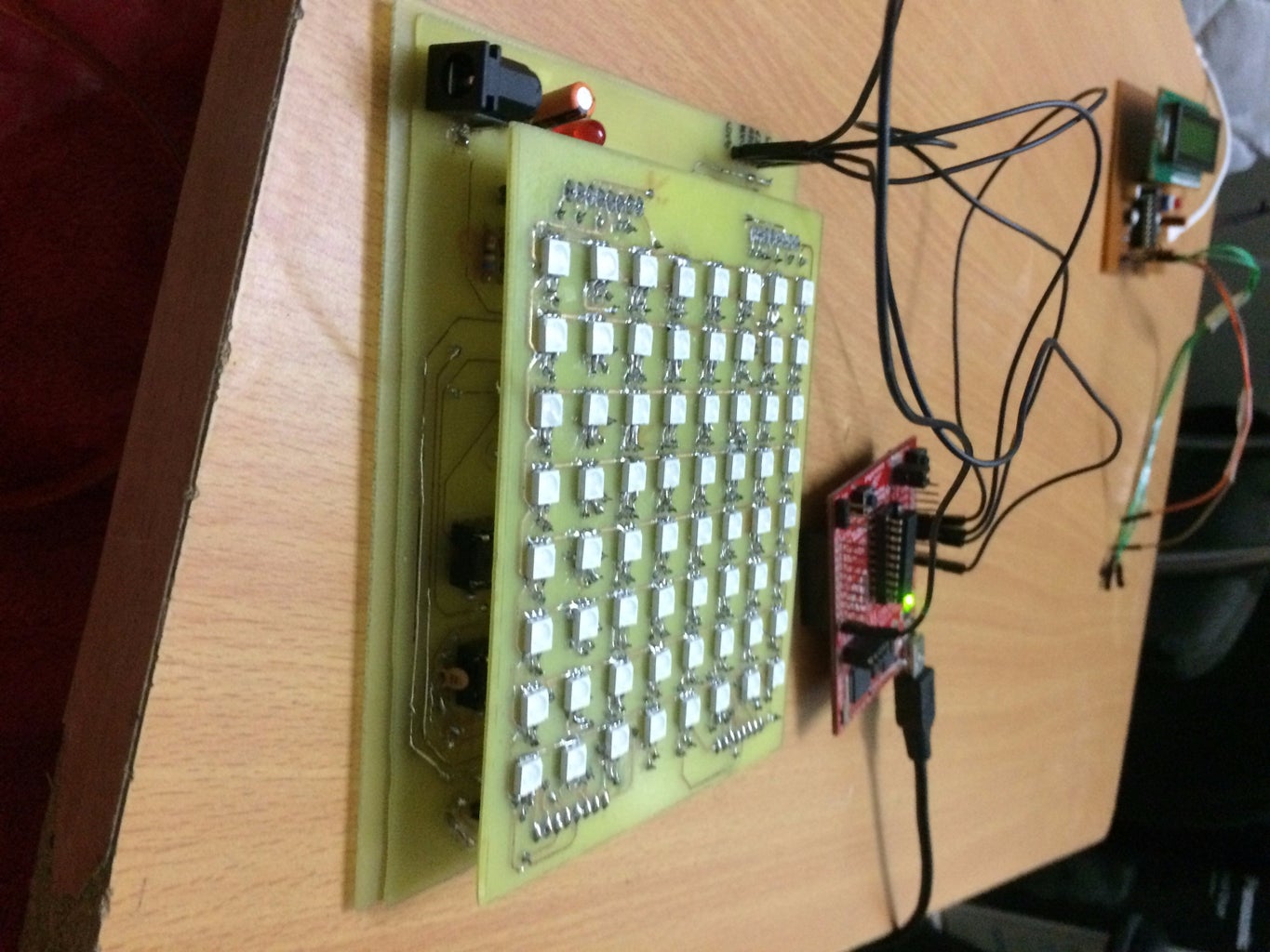
3. Once the board layout has been made, the only thing left in the designing of hardware part of the LED matrix is to fabricate the designed board. I have used Toner Transfer Method for fabrication.

Step 2: Designing of Driver Circuit for the LED Matrix
To drive a multiplexed LED matrix, high side drivers and low side drivers both are required, as the current requirements are high and cannot be met by the microcontrollers.
To have an average current of suppose 10mA through the LEDs, if we use row multiplexing we would need a peak current of 240mA through each LED for this particular board (to switch on all LEDs - thus a total of 8*3=24 rows). This current is provided by the high side drivers. However, the current sinking of the low side driver must be kept in mind, which in this case would be 240*8 mA. The resistors must be included keeping in mind the above calculations and the cut in voltage of the LED(1.7V for red, 2.6V for green and 3.3V for blue approx.).
To further reduce the pins required from the microcontroller, I have used shift registers and cascaded all 4 of them. For high side drivers I have used UDN2981. A adapter had to be used to provide Vcc to the high side drivers as the Vce saturation for the drivers was approximately 2V.
For low side drivers I have used ULN2803.
A connector has been provided where data, Vcc , ground , clock and latch for the shift registers can be given. By inclusion of this connector, the board can be interfaced with any microcontroller.
After basic calculations, schematic, board layout and fabrication must follow.
Step 3: Coding Your Microcontroller


Here, we code the microcontroller to refresh the LEDs at a constant rate. I have used Timer with interrupt enabled in the up mode (see MSP430 user guide for more information).
The code has been provided.


