

Introduction: Magpi: the Micro Arduino Gaming Platform Interface


Here's a retro hand-held gaming console I built with my son. It uses an Arduino micro-controller, a small LCD screen, push-buttons, a 3D printed case and home-grown "PC" board. It's really pretty easy to solder and put together. My son & I wrote two games and a drawing program for it. See the video for a quick demo. Enjoy!
Step 1: Parts List

Here's the parts list for the magpi itself:
- 3D printed case and "PC board": (https://www.tinkercad.com/things/dgZDHwdQxTX-magpi-complete)
- Arduino Pro Mini 3.3v (https://www.sparkfun.com/products/11114)
- Nokia 5110/3310 LCD (http://www.adafruit.com/products/338) this same LCD is available from Sparkfun, but their form-factor is a bit larger so I went with the Adafruit, and the case is custom designed for that. If you want to use the Sparkfun version you'll have to modify the case.
- 6 Square tactile button switches (http://www.adafruit.com/products/1010)
- 1 Tall tactile button switch (http://www.adafruit.com/products/1490)
- LiPo Charger Basic - Micro-USB (https://www.sparkfun.com/products/10217)
- 400mAh lipo battery (https://www.sparkfun.com/products/10718)
- SPDT Mini Power Switch. (https://www.sparkfun.com/products/9609 You can also use a slightly larger switch but then you need to use a different version of the bottom case)
- Break Away Male Headers - Right Angle (https://www.sparkfun.com/products/553)
- Wire & solder
In addition you will need the following tools:
Soldering iron, flush cutters for trimming wires after soldering, wire-strippers, needle-nose pliers to bend wires into place, hot-glue gun.
You will also need an FTDI adaptor to program the Arduino Pro Micro. I use this one from Sparkfun: https://www.sparkfun.com/products/9873
Step 2: 3D Printing the Parts


The case and PCB were printed on a PrintrBot Jr (v2) at .3mm layer height. The PCB and top case don't have any support material so they are pretty easy to print. The case bottom has a bunch of support which needs to be cleaned out. Message me if you are having trouble printing something, and I will get my son to help you. He's a pro.
Please note that if you are using Slic3r 1.0.0RC2 it might create support material too close to the upright walls of the case. We had to go back to an earlier version of Slic3r for it to work. You might be able to use skeinforge.
If you don't have a 3D printer, check the "3D print my thing" subreddit and someone will probably be able to print this for you much more cheaply that the big commercial 3D printing services. You can also try makexyz.com.
Step 3: Prepare the 3D Printed Parts


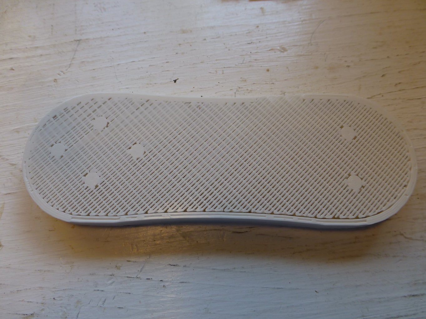


PCB
This project was and experiment for me in making a 3D printed mounting board for the various parts instead of having to have a standard PC board with the etching done. It felt like there were few enough connections that it would be pretty easy to solder with just plain wire as long as there was a decent support layout. The important thing was to get all the buttons in a fixed place so they wouldn't move around as you use the magpi. Because printing small bore holes is tricky (i.e. not precise) with our Printrbot Jr. V2, what I did was leave the very bottom layer of the print solid and then drill holes through it with a 1/16" drill bit (see photo). After you drill the holes insert a buttons an make sure the seat well.
Case
Clean out the support material in the top case. Start by passing a utility knife around the perimeter to clear the support material from the edges. Use needle nose pliers to pry up the support material. Be careful when pulling out the support material not to snap off the button backing supports. You may need to use a flat-head screwdriver to scrape off the last bits of the support material. This is most important in the areas where the battery, charger, and Arduino go so they fit. (See photos).
The top and bottom case are designed to snap together. It's a tight fit, so you may need to use a utility knife to trim the parts a bit so they fit. It's also a good idea to fit the LCD over the printed pins that go into the holes on the LCD circuit board to make sure they fit properly. You may have to trim them just a bit too.
Step 4: Wiring the Electronics

Here is the wiring diagram for all the electronics. In the subsequent steps I've described how put it all together so you probably don't even need the diagram because you should be able just to follow the instructions and look at the photos. In designing this I tried to choose pins to make the wiring as easy as possible, but of course other pin-choices are possible, you'll just have to modify the pin mappings in the magpi software.
I've assembled two different magpi's and my son has assembled a third, and we've done it differently each time, so feel free to assemble things in what ever order makes most sense to you. For example it might work better to solder all the wires to the Arduino first and then solder them to the buttons and LCD. Feedback appreciated!

Step 5: Mount and Solder the Buttons to the PCB


- Start by soldering all the ground connections on the buttons following the wiring diagram or the photos. I found it easiest to strip a little bit off the end of each wire and make a hook that I could loosely connect to the button lead. I use black wire for all of these.
- Next, solder the leads that will go from the buttons to the Arduino digital input pins. I use red wire for all of these.
Step 6: Solder LCD Wires


- Cut and strip seven three-inch strips of red wire and 1 of black wire.
- Bend the stripped end of a wire over at a 90° angle and insert it into a numbered hole on the LCD. (Hole number 1 is for the black ground wire.) Do this for each numbered hole.
- Put a piece of tape over the wires to hold them in place. Then, flip the LCD over, solder them in, and cut the excess ends off with flush-cutters.
Step 7: Prepare for Soldering LCD to Arduino


We need to figure out where the Arduino will sit in relation to the LCD so we can bend and cut the wires to the right size. This is a little tricky but not too bad.
- Take the top and and bottom cases and mate them together and use a sharpie to mark the spots on the top case where the large opening from the bottom case will meet it (see picture).
- Now place the PCB into the top case and draw lines extending from the marks you just made. This is where the Arduino will sit. (see picture)
- Now solder the male angle header to the Arduino. Trim off the extra bits of the pins that come through the Arduino.
Step 8: Solder the LCD to the Arduino


- Insert the LCD into the top case and then slide the PCB in place over it.
- Bend the wires neatly in a curve (see picture) so they cross over the line you drew in the previous step.
- Trim the wires from pins 3-7 to about a 1/4 extra past the line. Strip that 1/4 inch and then bend it up at a right angle.
- Solder the wires from LCD pins 3-7 to Arduino pins 2-6 (see picture).
- Now bend and trim the wire from LCD pin 8 and solder it to Arduino pin 9 (see picture).
- Now bend and trim the wire from LCD pin 2 and solder it to Arduino VCC pin. This pin is on the other side of the Arduino. (see picture).
- Finally, cut a 3 inch piece of red wire, and and solder it to the Arduino RAW pin. This wire should pass across the body of the Arduino (see picture). It will be attached to power switch.
Step 9: Solder the Button Wires to the Arduino


- Insert the LCD and Arudino into the top case making sure the LCD fits snugly onto the pins on the case.
- Slide the PCB in place between the LCD and the Arduino.
- Route the red wires from the up and down buttons so you can trim, strip and bend them to fit into pins 7 and 8 of the Arduino. Solder these in place. See photo.
- Route the red wires from the left and right buttons so you can trim, strip and bend them to fit into pins 10 & 11 on the other side of the Arduino. Don't solder these yet as it's easier to solder the other side all at one time.
- Route the red wires from the two big buttons to pins 12 & 13 of the arduino, and the wire from the small button to the A0 pin, trimp, strip and bend, but again don't solder.
- Route, trip, strip and bend the black ground wire from big button to GND pin on the arduino.
- Now fit all the wires into the pins, and make sure the Arduino is in position so that the angle header will be accessible through the hole in the bottom case!
- Solder all the pins, and then trim them with the flush cutters.
- Finally solder the black wire from the LCD to a ground pin of the one of the button black wires.
Step 10: Initial Testing

At this point, if everything has been correctly soldered, you should actually be able to boot the magpi!
Attach the FTDI adapter and upload the code from the Arduino IDE. You can download the code from github at: https://github.com/zippy/magpi
Follow the instructions in the readme to download and install the dependencies.
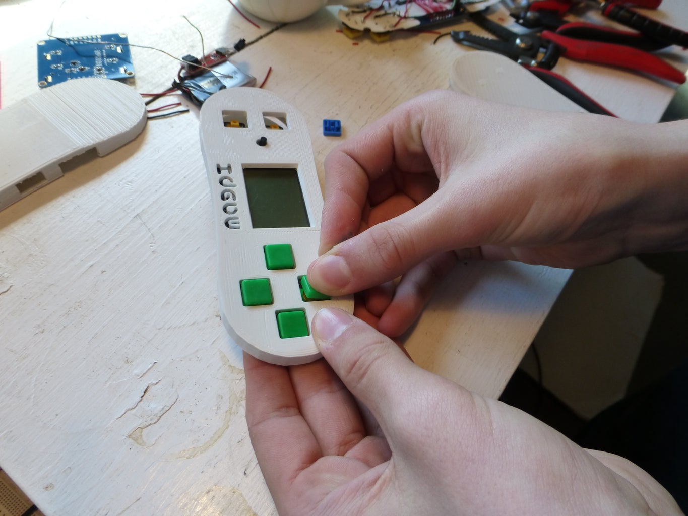
When you attach the FTDI adapter, the back-light on the LCD should turn on right away. Once you have uploaded the code, the magpi should reboot and show the splash screen and then go to the game selection menu (see photo). Test the buttons to make sure they all work as they should. If you soldered a button to the wrong pin, it might be easier to change it in software than re-solder.
Step 11: Solder the Power System in Place


- Put the the lipo charger and power switch in place, and route the red + wires from the Arduino and the lipo charger to the switch and a black wire from the lipo - terminal to the close button ground where it will be soldered. See picture.
- Solder the red and black wires you just routed trimmed and stripped into the positive and negative terminals of the lipo charger. See picture.
- Hot-glue the switch and lipo charger in place.
- Solder all the wires. See pictures.
- Fit the battery in place, wrapping the JST connector wire around it to keep it out of the way. I used electrical tape to hold it in place.
Step 12: Snap in Place and Play!

Now all you have to do is carefully bend the wires over and snap everything together snugly and you should be able to switch it on and play!
Once you have your magpi running, please write some games for it and send them our way. We'll add them to the github repo for everyone to see.

Participated in the
Arduino Contest


