

Introduction: Make an Ultimate Helping Hand Jig


Here is a helping hand jig that is useful for soldering, gluing, painting and macro photography. It is highly configurable to hold various small objects in many positions.
While this version is 3d printed, it could also be made using traditional hand methods.
Step 1: How It Works


While this may not be the ultimate jig for everyone, I have found it very useful for soldering and gluing small projects. It can be adapted with different grippers for different kinds of projects.
I was experimenting with various ways of 3d printing self-assembling hinges for future use in robot arms and legs. Making some hinges that can lock in place seemed like a good way to test the strength of the structures.
The helping hand has six configurable, lock in place, arms with interchangeable grippers. While this version was 3d printed, a similar jig could be made using acrylic or other plastic sheet material. It could even be made out of thin plywood. Three layers could be laminated together to make the arms.
Step 1 pic shows it set up for soldering with flashlight and magnifier. Pic 2 shows it folded up.
Step 2: Tools and Materials

I used a Makerbot Replicator 2 to print the parts in PLA plastic. If you do not have access to a 3d printer you could make the jig by laminating hand cut sheet plastic or plywood.
100% silicone caulk and corn starch to make Oogoo. Details on making Oogoo can be found here:
https://www.instructables.com/id/How-To-Make-Your-Own-Sugru-Substitute/
sheet metal
24 4-40 x 1" round head screws and nuts
6 4-40 x 3/4" round head screws and nuts
2 1/2" diameter x 3/8" long neodymium magnets
Step 3: Making the Arms


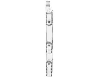
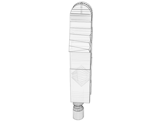
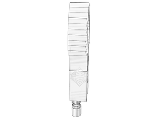
This jig was designed in 123D Design beta. Step 3 pic shows a drawing of the arm. Pic 2 shows a closeup.
Each arm is printed as one self assembled piece (arm.stl). The conical pins hold the hinges together even without the screws.
All 3d printed pieces were printed using a Makerbot Replicator 2 with the following settings:
Standard resolution with a raft
10% infill
2 shells
.2mm layers-standard resolution
If a space of .01" or larger is left between movable parts, all kinds of movable mechanisms can be 3d printed including hinges, shafts, and bearings.
Print the Knobs
The knobs (knobs4-40.stl)are designed to fit a 4-40 size screw tightly. Do not over screw and strip the hole.

Step 4: Making the Interchangeable Grippers


The gripper halves are printed as one piece. A rubber band donut provides the gripping power.
Pic 2 shows the two halves of a gripper and the silicone donut.
Pic 3 shows how the silicone donut was cast using 3d printed form: donut.stl. Oogoo works well to cast the donut. A 3 silicone Caulk to 1 corn starch by volume produces a silicone that will set up in two or three hours. More details on using Oogoo to make rubber bands can be found here: https://www.instructables.com/id/7-Things-To-Fix-Or-Do-With-Oogoo/
Most of the rubber donuts were made using Dragon Skin 20 silicone which pours real nicely and is available from Smooth-On.com.

Step 5: Making the Magnetic Grippers

The magnetic grippers work by holding small components against the silicone pad on the base.
You can print out maggrip.stl and then glue in 1/2" diameter magnets. Or you can make your own magnetic grippers in a shape that suits your needs.
Attachments

Step 6: Making the Base


The base can be printed using base.stl
The bottom of the base has been hollowed out to allow for a piece of sheet metal to be glued in with silicone caulk. The thicker the sheet metal, the better it will attract the magnetic grippers.
A 1/16" thick silicone pad can be cast using Oogoo and the mold: hexmold.stl. It can then be glued on to the base using silicone caulk. This provides a grippy surface so components can be easily held in place.
Step 7: Soldering


Step 7 pic shows how a surface mount LED can be held in place to solder by the weight of a sharp screw pivoting on an arm. Metal nuts can be put on the screw above the gripper to increase the pressure.
Pic 2 shows how the magnetic grippers can be used to hold wires and small components to solder them. The silicone pad on the base can handle the heat of the soldering without melting.
See also the step 1 pic for a full soldering setup.
Step 8: Painting and Photography


Pins or nails can be used to support objects in the arms while they are spray painted top and bottom. A plastic bag can cover the jig with just the pins sticking through.
Pic 2 -The jig can also be used to hold objects or a camera as an aid in macro-photography.
Step 9: Other Possibilities


The step9 pic shows a couple of experimental helping hand robots I designed that used friction ball joints to hold things in place. Magnets in the feet hold them upright. While they worked fairly well, they could not hold much weight without slipping. So I started to experiment with locking joints.
Pic 2 shows an experimental arm that uses a ball joint for the gripper. It was all printed as one piece. While it worked, it had problems. When the screw was tightened, it tended to permanently dent the ball. So a much larger joint would have to be used that squeezes uniformly around the plastic ball.
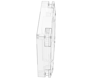
Pic 3 shows a puzzle box design with hidden conical hinges. The box is printed in one piece.
Pic 4 shows the printed box closed.

Third Prize in the
Portable Workstations Contest

Participated in the
Full Spectrum Laser Contest

Participated in the
Gadget Hacking and Accessories Contest


