

Introduction: Make Your Own Development Board With Microcontroller


Did you ever want to make your own development board with microcontroller and you didn´t know how .In this instructable I will show you how to make it.All you need is knowledge in electronics, designing circuits and programming.
If you have any questions or problems you can contact me on my mail:iwx.production@gmail.com
Visit my youtube channel:
https://www.youtube.com/channel/UCuS39O01OyPeChjfZm1tnQA
So let's begin.
Step 1: Materials


-Bascom AVR for programming
-Attiny2313A-PU 8-bit
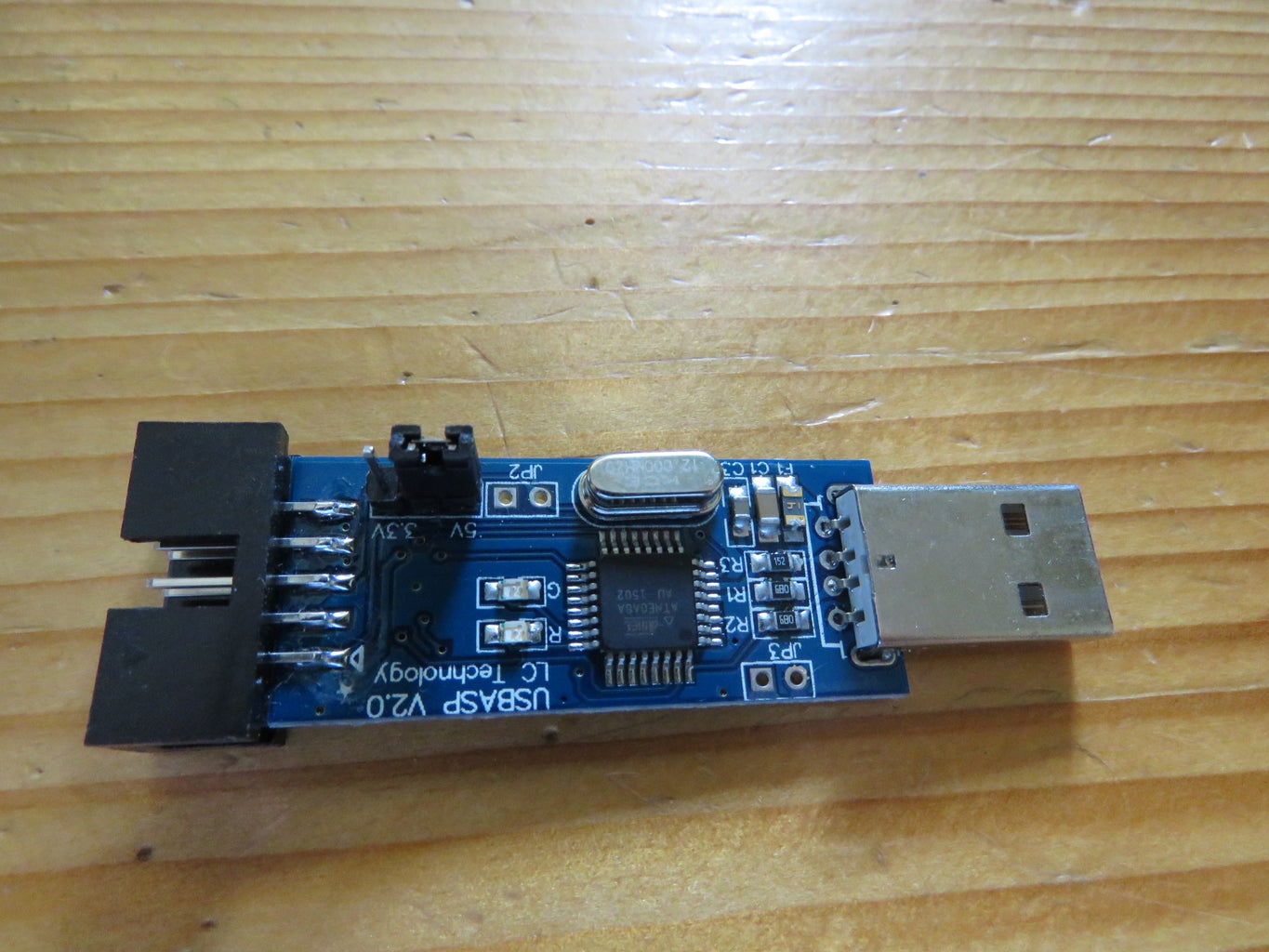
-USBasp AVR Programmer
-Stabilisator L78L05.This is stabilisator that stabilise voltage to 5V
-two 100nF condensators
-two 33pF condensators
-one 10k ohm resistor
-crystal 11MHz
-8 red LED diodes
-eight 100 ohm resistors
-11 pins
-10 pin ISP Male Connector Header
If you want you can also make relay outputs.For one relay output you need:
-12V DC relay
-1k ohm resistor
-1 LED diode
-1 Rectifier Diode IN4001
-NPN BC238 transistor
-three pins
Attiny2313A
In this project I used 8-bit chip from ATMEL family which can be also found on Arduino.It belongs to TTL family so it runs on 5V+.
It has 12 digital outputs or inputs.Pins 2,3, from 6-9 and from 11-16
Pin 12 and 13 can be also used for analog values
Pin 1 is reset
Pin 4 and 5 are connected to GND with 33pF condensators.
Pin 10 is GND
Pin 17 is MOSI
Pin 18 is MISO
Pin 19 is SCK
Pin 20 is Vcc+
For programming this chip I used USBASP AVR Programmer
Step 2: Wiring


You can help yourself wiring this by picture I posted.There are two 100nF condensators on picture but this time I used only one.
5V+ are connected to stabilisator L7805 then there is one 100nF condensator for smoothing voltage.Voltage goes to pin 20 and to pin 1 through 10k ohm resistor.Pin 4 and 5 are connected to GND with 33pF.Crystal is connected parallel between pin 4 and 5.
Resistor and LED diode on pin 11 are just for exemple.
How to connect 10 pin ISP Male Connector Header
You have numbered pins on picture so you will know where to start.
Pin 1 is connected to MOSI (pin 17 on Attiny 2313)
Pin 2 is connected to Vcc+
Pin 3 no connection
Pin 4, 6, 8 and 10 are connected to GND
Pin 5 is connected to reset pin on Attiny2313 (pin 1)
Pin 7 is connected to SCK (pin 19 on Attiny2313)
Pin 9 is connected to MISO (pin 18 on Attiny2313)
Relay output
Relay output can be used for electrical consumers with bigger current and voltage.Relay is controlled with transistor.Base of transistor is connected to digital output, collector is connected to relay circuit and emittor is connected to GND.Rectifier Diode IN4001 is used for protecting the circuit.LED diode is in this circuit so you can see when relay is ON.
Step 3: Fabricate the Circuit Board

I made this circuit by myself.For drawing the circuit is used SprintLayout.This is program for drawing circuits, in this program you have all the dimensions of electronic components so basicly you can make circuit for everything you want.
For engraving this board is used CNC engraving milling machine.I used normal board for circuits which is cotted with copper on one side.When board was finished I polished it with very fine sand paper.Then I mixed industrial alcohol and rosin in powder.With this mix I then coatted copper side to protect it.


