

Introduction: Make a 1-2 UH Output Air Core Inductor for Audio Amplifier


The output of almost all audio amplifiers contains a circuit of an inductor and resistor in parallel. The inductor is there to enhance stability in the face of speakers that present a capacitive load. The resistor is there to dampen potential ringing or oscillation caused by the interaction between the inductor and the speaker capacitance.
The inductor in this circuit must be an air-core inductor as magnetic cores wreak havoc with audio signals. It is typically in the 1-2 uH range.
Step 1:

Here is what you will need.
1. Various PVC parts: a small section of 3/4" pipe; a T fitting; a fitting usually used to join/glue two pipes in a straight line, but cut into 2 pieces (I used a band saw) so they can slide onto the 3/4" pipe; and a large pipe fitting that I believe is a compression joint (not sure exactly what it is but they are easily found at Lowe's). I did not use PVC glue but you may want to on the T-handle.
2. 14 Gauge coated magnetic wire. I chose this gauge to minimize the resistance of the wire - the amplifier I am building is 200W per channel so I need a very heavy gauge.
3. Some 3/4" electrical tape
4. Tools: Not shown in picture but you will need wire cutters, box knife, and scissors. A drill and small drill bit. A band saw or hack saw to cut PVC pipes and fittings.
5. Optional - a meter for measuring inductance.
Step 2:

Put the T-fitting onto the 3/4" pipe - it will be your turning handle. Slide the pipe onto the compression joint (again, if that is what it is called) making sure that the 3/4" pipe is loose enough to turn.
Step 3:

Slide one of the fitting pieces (ones I mentioned that I cut on a band saw) onto the 3/4" pipe and drill a hole in both the fitting piece and the 3/4" pipe. These holes should then be lined up on top of each other - they are used to hold the magnetic wire so you can begin winding the coil.
Step 4:
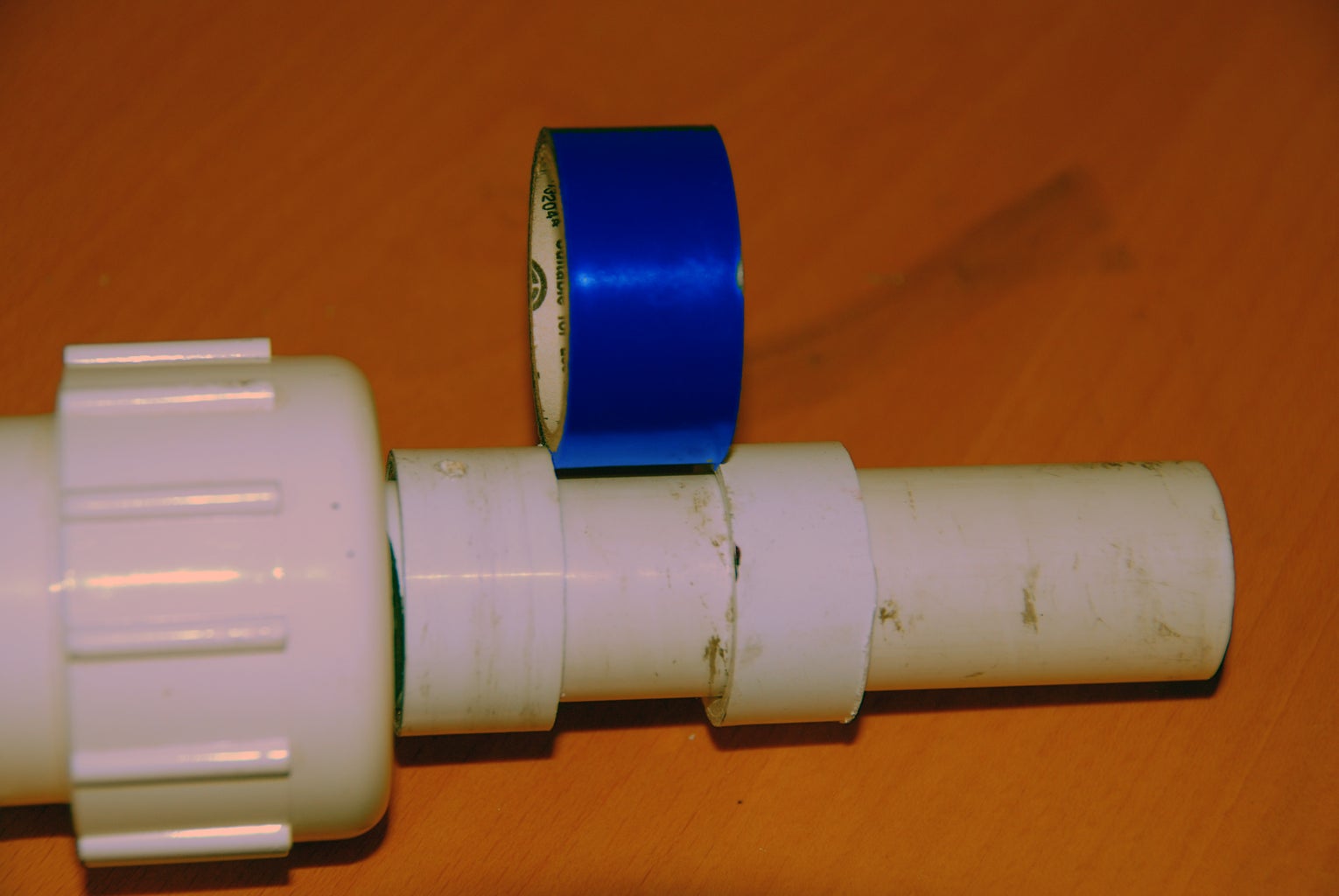
Slide the other fitting piece onto the 3/4" pipe and use the electrical tape to set the width between the two fittings.
Step 5:
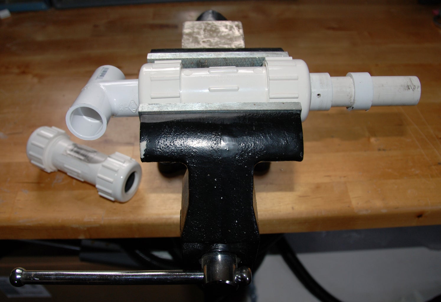
Insert the entire assembly into a vice and squeeze the compression fitting tightly so it cannot move, but loose enough that the 3/4" pipe can turn. You can see from the picture that the same scheme presented here can be used for smaller diameter pipe - see the smaller fitting on the table.
Step 6:

Next, insert the magnetic wire into the hole we drilled earlier in the 3/4" pipe and the left fitting, and begin to wind the wire by turning the T-handle PVC piece on the left while making sure the wire is tightly wound.
Step 7:
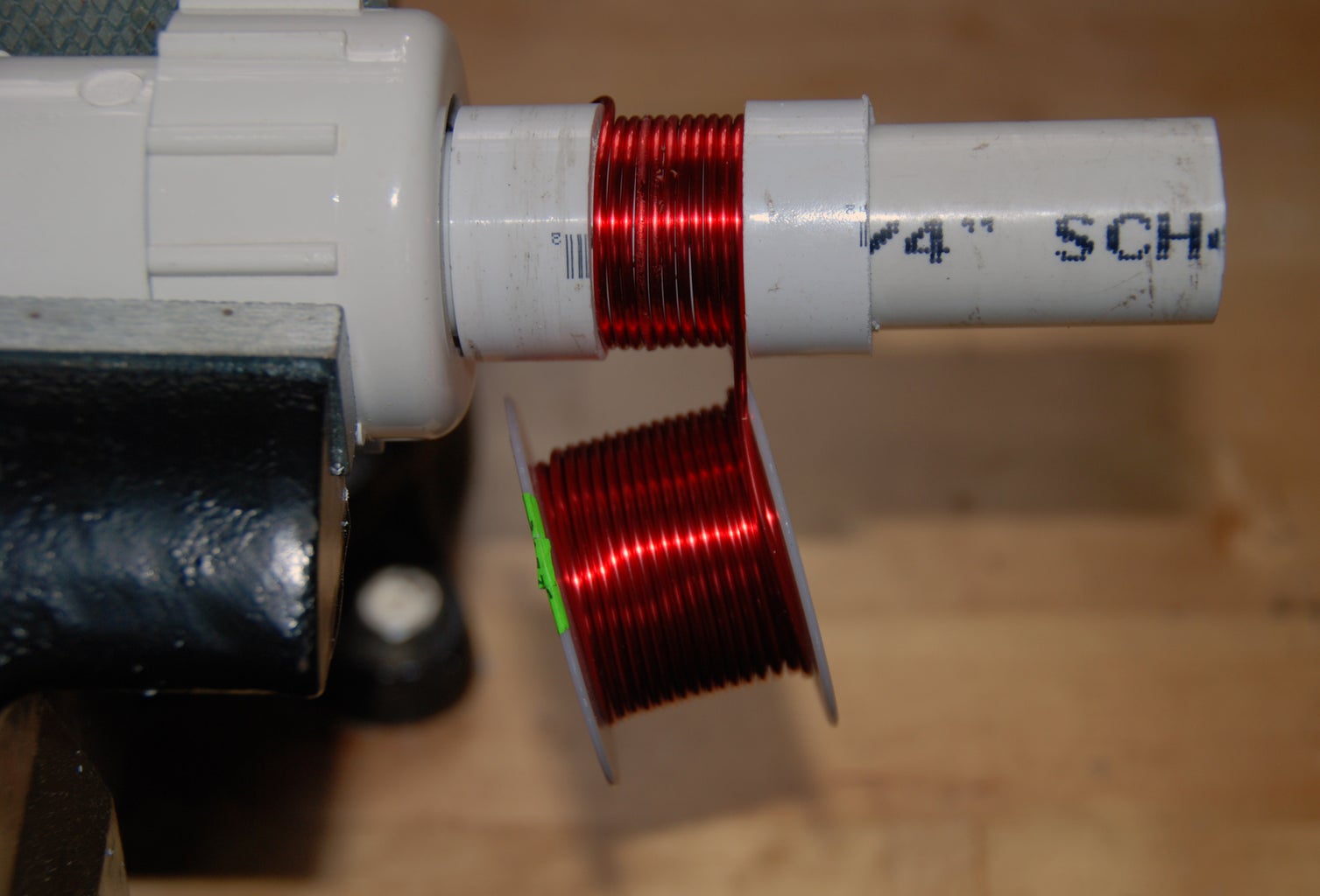
Wind until you fill the entire width between the two fittings, making sure to keep the coils as tight as possible.
Step 8:

Before cutting the wire, begin to wrap the tape around the coil. I do two full turns around the coil with electrical tape.
Step 9:

Cut the wire, leaving enough lead wire for the inductor to be inserted into a Printed Circuit Board.
Step 10:

After carefully removing the wire initially put into the drilled hole in the PVC, carefully move the taped coil off of the 3/4" PVC pipe.
You now have the final inductor - the blue electrical tape keeps the wire tightly coiled and adds a little refinement (my opinion of course).
Step 11:

Because the magnetic wire used here must be coated (so none of the coals actually connect electrically to each other), we must scrape it away if we are to use the inductor. Simplest way is using a knife as pictured.
Step 12:
Measuring the inductor, we find it to be 1.6uH, right in the 1-2 uH range we were after!
I say the meter is optional because I have made a dozen of these inductors and they always come in around 1.5uH.
Step 13:

Here is the first inductor I made using this rig - it is in a prototype amplifier board and works perfectly!
If you do not need to use 14 gauge wire for your amplifier, you can experiment with a smaller gauge of wire, more or fewer number of wire turns, and/or a smaller PVC pipe to get 1-2 uH from the smaller gauge wire.


