

Introduction: Bitcoin Price Ticker (almost) From Scratch Using Arduino As ISP


Hello everyone!
I decided to create this tutorial on how to make a Bitcoin Price Ticker. Well, this is only a prototype and I will make a smaller edition with a more pleasant design and some other features at a later time. However, this serves as a nice proof of concept and hopefully it will give you some ideas for your own improvements.
This Bitcoin Price Ticker will show the price of Bitcoins in 3 different currencies (USD, EUR & GBP), and it will update the price every minute. I fetch the price from http://coindesk.com every minute which provides an average price based on multiple markets.
I will show you how to make this entirely from scatch(well almost), building your own arduino replica with an ATmega328 microcontroller to control everything, and wrapping it all in a nice casing. The only thing we won't make ourselves is the Adafruit CC3000. I have tried to explain all the steps as detailed as possible, without forcing you to spend hours reading. However, feel free to ask in case you have any questions or concerns.
Feel free to visit my blog/website for more projects and other things: http://www.cavaleri.dk
Have fun with this project! (I sure did)
Step 1: Gather Materials
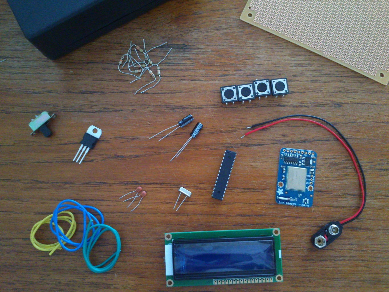


Obviously you will need a couple of things for this instructable. I will go ahead and list out the things you need, apart from the obvious work tools (soldering iron, solder, cutter bar etc).
Stuff you need:
- ATmega328P-PU (The ATmega328-PU will also work, but is a little more complicated. It will be a lot easier if you find it bootloaded with Arduino, but it is not a requirement)
- 5x 10k Ohm resistors
- 220 Ohm resistor
- 7805 Voltage Regulator 5V
- 2x 10uF capacitors
- 2x 22pF capacitors
- 16 MHz crystal
- LCD display 16x2
- 9V battery connector
- 4 switches (buttons) (I used tact switches)
- Wire (and quite a lot of it)
- Plastic box
- Prototyping board 120x80mm (I used 1½ in total)
- Adafruit CC3000 Breakout.
You can get all of the above except the CC3000 from Tayda Electronics http://www.taydaelectronics.com
The CC3000 can be found on Adafruits website http://adafruit.com but I got mine off of Ebay.
Price:
Adafruit CC3000 ~$40
Everything else: $20
Total: ~$60
Step 2: Breadboard Testing


I suggest you to build everything on a breadboard first using your Arduino (I used the Arduino UNO). Then you will be able to test if the code works, and that you are able to connect to your WIFI (if you entered the wrong credentials etc.). These images will show you how to set it up using the CC3000 shield, but it will work with the breakout as well. Simply follow the directions below to know which pin goes where.
Adafruit CC3000
As you see in the image I used a CC3000 shield I had laying around, but you will be able to use the breakout as well. If you are using the breakout your pins should look like this:
- IRQ -> Arduino 3
- VBEN -> Arduino 5
- CS -> Arduino 10
- MOSI -> Arduino 11
- MISO -> Arduino 12
- CLK -> Arduino 13
- Vin -> power
- GND - > Ground
LCD Display
On to the display. I have numbered the pins on the display from 1-16 and from the bottom up. Have a look at the image as well, in case you want to confirm the setup. As you can see on the image, I have not added any female pin headers on my CC3000 shield, which makes it a little difficult to connect the wires. Try bending the end of the wires a little to make a hook, if you are facing the same problem - it worked perfectly for me. Just make sure they do not connect underneath the shield.
- LCD 1 -> Ground
- LCD 2 -> Power
- LCD 3 -> Ground (Or you can add it to a potentiometer, which connects to power and ground. This is to alter the contrast of the screen. I however got the best result connecting it directly to ground.)
- LCD 4 -> Arduino 8
- LCD 5 -> Ground
- LCD 6 -> Arduino 7
- LCD 11 -> Arduino 6
- LCD 12 -> Arduino 4
- LCD 13 -> Arduino 9
- LCD 14 -> Arduino 2
- LCD 15 -> Power through a 220 Ohm resistor
- LCD 16 -> Ground
Switches
Lastly you add your switches/buttons over the center-rail of the breadboard. Now connect one leg to power and the other to ground through a 10k Ohm resistor. The leg opposite of the resistor goes to the Arduino pins. I did not have enough space on my small breadboard, so I had to get creative and use wires with female pin headers to connect my 4th switch to the Arduino. I used the Analog pins because we are running low on Digital pins on the arduino. I used A0, A1, A2 & A4 but you can use any you like. Just remember to alter the sketch/code accordingly!
Upload sketch
All we need to now is upload the sketch. I have commented each section of the code but most is in Danish. However, it should be easy to understand from the code itself. I will change it to a English version when I get some spare time. Feel free to make any changes, and I would love to see what you did. It is a rather long piece of code and instead of copy pasting it, I have uploaded it here.
You will need to change the details of your WIFI. The following lines need to be changed:
#define WLAN_SSID “Network_name”
#define WLAN_PASS “Passphrase”
#define WLAN_SECURITY WLAN_SEC_WPA2 (Only change this if you are not using WPA2)
The code/sketch is certainly not perfect but it really gets the job done. You are more than welcome to go ahead and make any improvements. For instance, I did not add any debouncing for the switches but only a small delay to prevent them from getting pressed multiple times on a single click. It worked perfectly for my switches but that would be a good place to start, especially if your buttons make connections even when you do not press them. Please upload your example and make a comment about it. I will definitely add any good improvements to this code.
Once everything works as it should, go ahead and clear your breadboard to make room for the next step.
Attachments

Step 3: (optional) Bootload Your ATmega328


If you do not have a ATmega328 with Arduino preloaded, you will need to program it manually. I found a very useful guide to bootload the ATmega328P-PU (you can also use the ATmega328-PU but it is slightly more complex), and I have summarized it here. Be sure to check the original tutorial in case you have any problems, if you are using the ATmega328-PU or if you are looking for a more detailed guide.
https://www.instructables.com/id/Bootload-an-ATmega328/
For this step you will need:
- ATmega328P-PU (or ATmega328-PU)
- 2x 22pf capacitors
- 0.1 uf capacitor
- 16 MHz crystal
- 220 ohm resistor
- Wires
Start by programming your Arduino as an ISP(In-System Programmer). Open the Arduino IDE and find the ArduinoISP sketch(Files->Examples->ArduinoISP). Make sure you’ve selected the UNO under the boards menu. Now go ahead and upload this sketch to your Arduino board.
Place the ATmega328 in the center of your breadboard. Then connect pin 7 to power and pin 8 to ground.
Now connect the 16 MHz crystal between pin 9 & 10 on the ATmega, and add the 22pf capacitors between the crystal and ground.
Connect pin 20 & 21 on the ATmega to power and pin 22 to ground.
Connect pin 1 on the ATmega to power through a 220 ohm resistor.
Now make these connections between your Arduino board and the ATmega:
- Arduino pin 10 -> ATmega pin 1
- Arduino pin 11 -> ATmega pin 17
- Arduino pin 12 -> ATmega pin 18
- Arduino pin 13 -> ATmega pin 19
Time to burn the bootloader!
Open the Arduino IDE and change your settings.
- In Tools->Boards, select the Arduino UNO.
- In Tools->Serial port, make sure the correct port is selected.
- in Tools->Programmer, select the “Arduino as ISP” option.
Now you’re all set up. Select the option “Burn Bootloader” from the Tools menu. A message will show saying “Burning bootloader to I/O Board (this may take a minute)”. After a little while it will confirm that it has been loaded. Now you will be able to upload the Arduino sketch to your ATmega.
Open the sketch and click: File -> Upload Using Programmer, and the sketch will be uploaded to the ATmega328.
On to the next step!
Step 4: Cut the Case
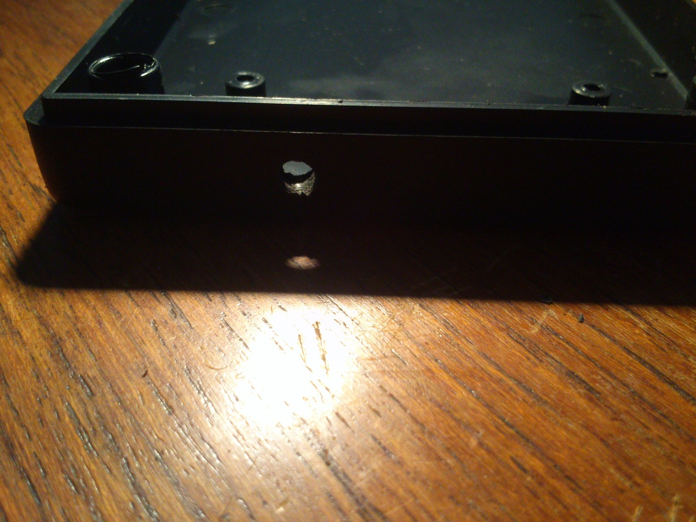

Go ahead and make 2 holes on the lid of the case. Measure the size of your LCD and the 4 switches when next to each other, and cut the appropriate holes. I also cut a hole for the power cord for easy battery change, but you can keep the battery inside the box if you want.
I used a handheld power drill to drill/cut the holes because I did not have any power jigsaw, and as you see the results could be better. It will do fine for this prototype though.
Step 5: Solder Everything Together


This is where things get interesting! We will start out by making a very simple arduino replica, a LCD module with wires and a module with the switches. Then we will solder everything together in the end. I based my design on this instructables on how to make a “Arduino on a Board”: https://www.instructables.com/id/BaW-Bot-Part-1-Build-an-Arduino-on-a-Board/
Feel free to use this instructables to get a more detailed explanation on how everything fits together. The image on Step 3 is especially useful! I decided to do it like a breadboard, and have a “rail” for power (+ve) and and a rail for ground (-ve). I did it like this to make it easier to understand and see all the individual connections.
Please refer to the above images for clarification on all the connections.
Adjust size of prototyping board
I had to cut a bit of the prototyping board to make it fit in the box. Initially I also wanted to screw it on to the bottom of my plastic case, but I ended up using glue instead. That’s why you might notice 4 black markings on the board, these were meant to let me know where the screws goes.
Power connections
Our first step is to regulate our power connection to a constant 5V which is needed for the ATmega328, because we are using a 9V battery to charge this project. Start by soldering the end of your power supply connector to the board. Most likely the red wire is power and the black is ground.
Next you need to add a 10uF decoupling capacitor across the pins. It is important that you place the negative side of the capacitor to ground and positive to power. The negative side pin is indicated with a white stripe or a –ve sign.
Now add the voltage regulator. Make sure that the voltage connects to the input and GND to ground. Please check the datasheet to make sure which pins is input-GND-output. Now connect the other 10uF capacitor to GND and output. Again, make sure that the negative pin goes to ground and positive to output.
Add the microcontroller
So far so good. Next step is adding the ATmega328 to the board. Place it with the notch/pin 1 dot in the direction of the power connections.
Now connect Pin 7 to power and Pin 8 to ground. Solder them on to 2 different rows and these will be markers for which rows are power and which are ground. Refer to my image for clarification.
Next you want to add the crystal between Pin 9 & Pin 10, and add 2 22pF capacitors between each leg of the crystal and ground.
Then go ahead and add a wire between Pin 20 & 21 to power, and a wire between Pin 22 and ground. These pins are on the opposite site and it makes sense to keep them there. That way we get another rail of +ve and –ve on the opposite site.
Lastly add a 10k Ohm resistor between Pin 1 and power. This is not in my images because I added it at a later point, but go ahead and do it now so we don’t forget. That’s it! We’ve created our very own simple Arduino replica.
Adding the CC3000
Now it’s time to attach the CC3000. I chose to solder it directly on to the prototyping board, but you are free to do alterations here if you want to easily remove it at a later point in time. Once you have soldered it on to your board, it is time to make the necessary connections.
Follow this schema to see which pins on the CC3000 goes where:
- IRQ -> ATmega Pin 6
- VBEN -> ATmega Pin 11
- CS -> ATmega Pin 16
- MOSI -> ATmega Pin 17
- MISO -> ATmega Pin 18
- CLK -> ATmega Pin 19
- Vin -> power
- GND - > Ground
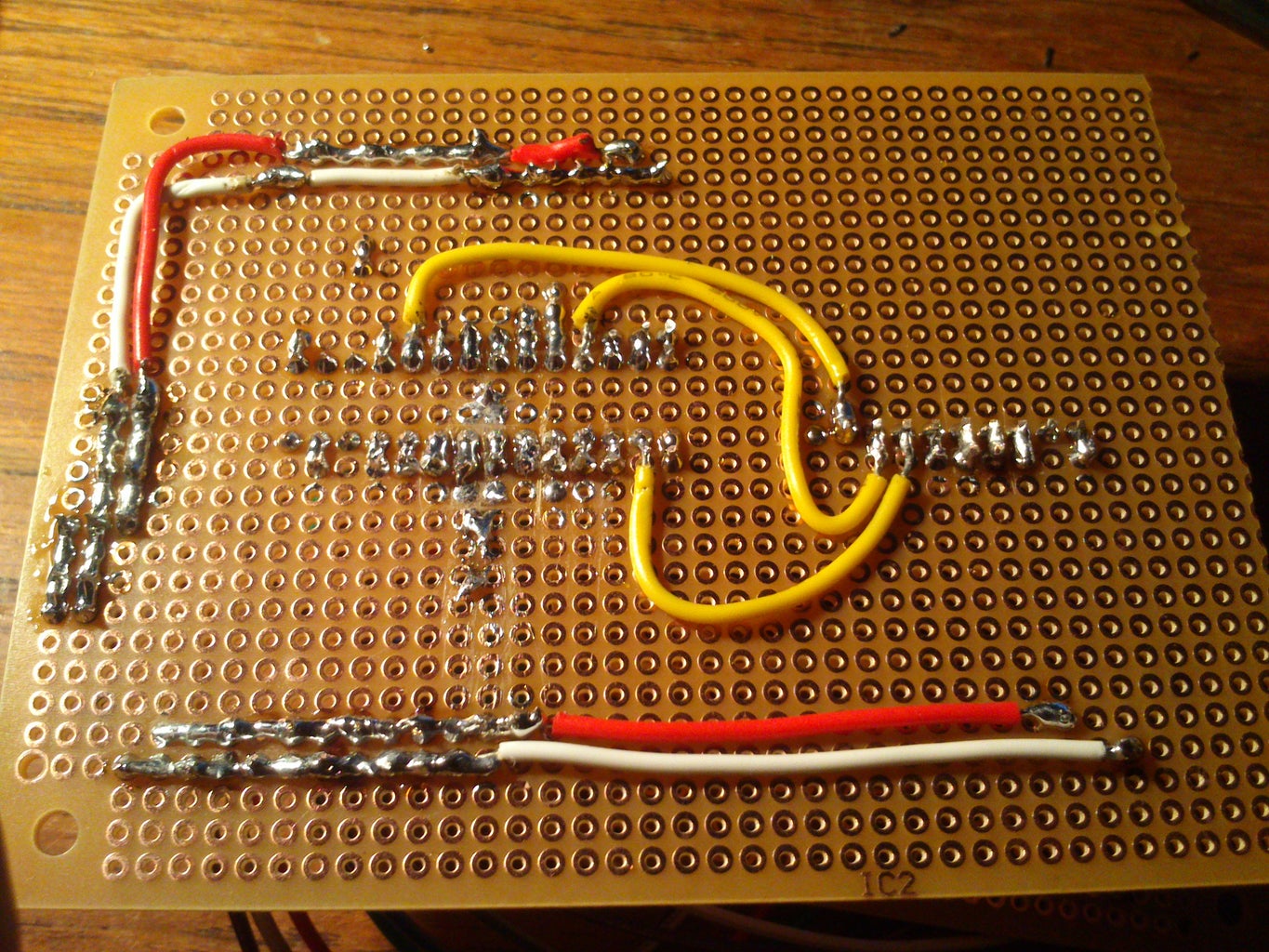
I made the first 3 of the connections on the bottom of the board instead, but you will be able to see them on a later image if you scroll down. You will be able to recognize them from the yellow wire I used.
LCD Module & Switch Module With Wires
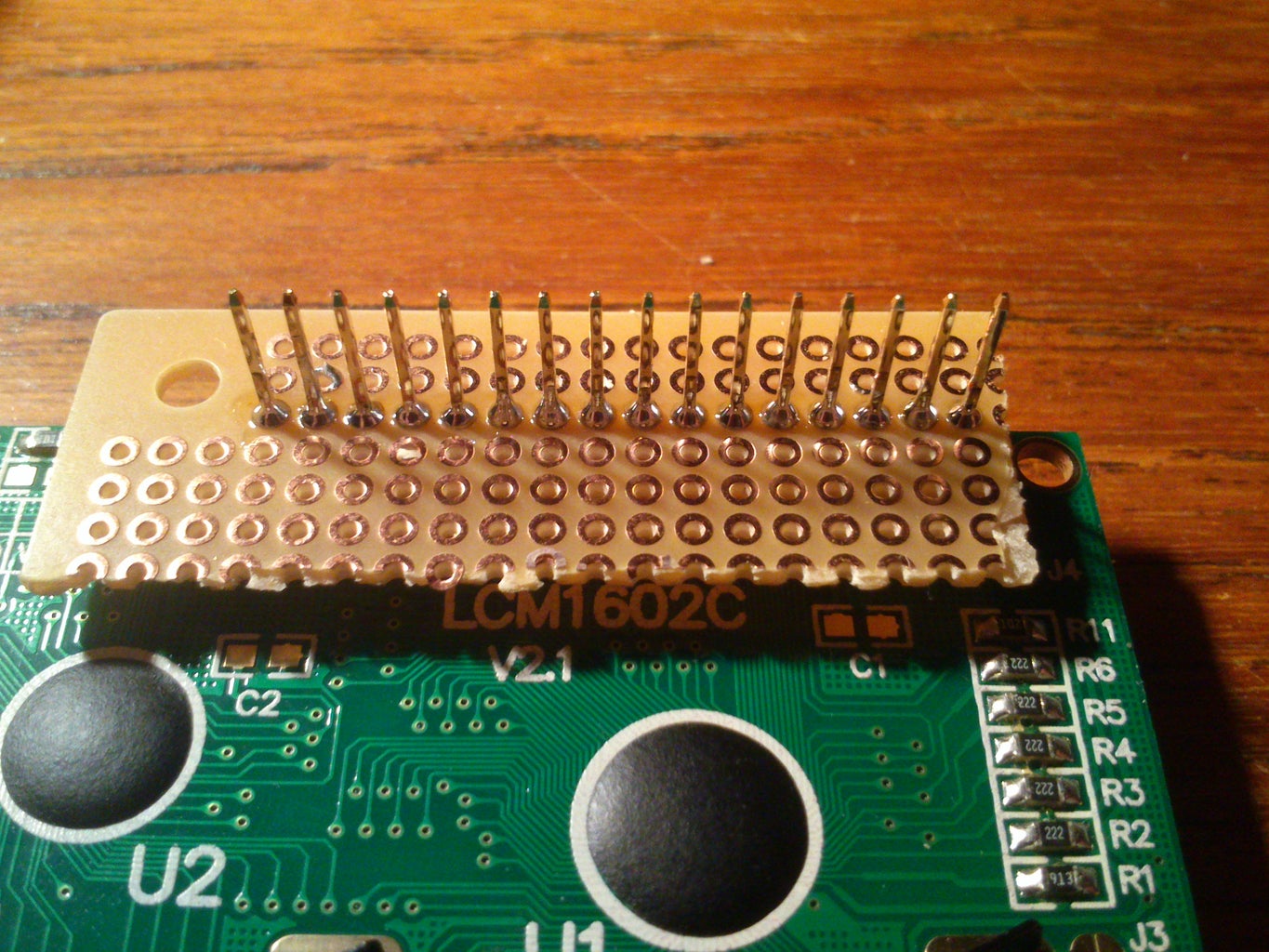
Cut out a small piece of a new prototyping board to use for connecting the wires. Alternatively you can connect them directly to the LCD, if yours did not come pre-soldered with pin-headers. I used an older display which was already soldered on to pin headers.
Solder the LCD to the small prototyping board, and add wires next to the first 6 pins and last 6 pins.
(Respectively pin 1, 2, 3, 4, 5, 6, 11, 12, 13, 14, 15, 16)
And make the necessary connections.
Now go ahead and do the same for your switches/buttons. Add a wire to 3 of the legs for every button.
Assembling the pieces
This will be the interesting step where we fit everything together nicely, and we will be almost done. At this point we have 3 “large” objects - the main board, our LCD and our switches. So let us get on with it and start out with the display.
It is a little difficult to see the connections on the image, seeing as my wires are a real mess(!), but I will describe the connections here. I use the same order as in the breadboard example – from bottom(1) to top(16):
- LCD 1 -> Ground
- LCD 2 -> Power
- LCD 3 -> Ground (Or you can add it to a potentiometer, which connects to power and ground. This is to alter the contrast of the screen. I however got the best result connecting it directly to ground.)
- LCD 4 -> ATmega Pin 14
- LCD 5 -> Ground
- LCD 6 -> ATmega Pin 13
- LCD 11 -> ATmega Pin 12
- LCD 12 -> ATmega Pin 6
- LCD 13 -> ATmega Pin 15
- LCD 14 -> ATmega Pin 4
- LCD 15 -> Power through a 220 Ohm resistor
- LCD 16 -> Ground
Lastly add the “switch module”. The side with only 4 wires goes to the analog pins on the Arduino. I used A0, A1, A2, A4 and it will result in pin 23, 24, 25 & 27 on the ATmega328. The 4 wires opposite of those which goes to the ATmega should go to ground through a 10k Ohm resistor. The rest goes to power.
At this point it becomes obvious that I had to desolder my power cord and fit it through the hole before continuing.
Finish power connections
Now go ahead and solder everything on the back side together, and make the +ve and –ve rail I mentioned before. I waited until the end to save on wires so I would be able to use solder for as much as possible. As you can see on my images, my soldering work is horrible to say the least, and I hope you will do a better job. However, there were no lose connections or short circuits so it will do well enough.
This is the nerve wrecking moment! Cross your fingers, pray to your god and do what is necessary before attaching your battery. If your display lights up, you’re certainly on the right track. Check that the CC3000 breakout LED is on as well. Yes? So far so good. Now just wait and see if it fetches the price. Once it does, go ahead and test each of the buttons to confirm they are working. If anything doesn’t work the way it should, then please go ahead and check your wiring. Otherwise go ahead and move on to the last step.
Step 6: Fit Everything in the Box

Brilliant!
All we need to do is put everything in the case and seal it. I initially wanted to screw the display and buttons on to the lid, but I was unable to find any proper nuts so I ended up using super glue. I glued the switches on to the inside of the lid and the display I glued on the outside. However, suit yourself and do it any way you feel is better. I also glued the “main” part to the bottom instead of screwing it tight.
Close the lid and screw the 4 screws tight to make sure everything stays in place and simply wait for all the glue to dry. Once it’s dry you’ll have yourself a fully functional homemade Bitcoin Price Ticker!
I would love to hear if you have any criticism, suggestions or some kind of concern. This is my first instructable/tutorial on this site, and I would love to improve on my narrative.
If you decide to do this project, then I wish you the best of luck! It surely has been fun for me and I would love to see the result of your work as well.

Participated in the
Arduino Contest

Participated in the
Full Spectrum Laser Contest


