

Introduction: Make a Contact Microphone


A contact microphone is a type of microphone that picks up vibrations from contact with objects, as opposed the the more common type of microphone that picks up pressure waves in air. Here's a demo of a contact mic attached to an alarm clock, along with finger tapping on the table about a foot away from the clock:
In this Instructable, we show you how to construct a professional quality contact mic that is very rugged and sounds good. It has a 1/4" female jack so that you can connect it to an amplifier with a standard guitar cable.
This particular version of a contact microphone was designed for the premier of The Immortal Flux, a composition for drum kit and prepared drumhead orchestra written by Glenn Kotche, drummer for the band Wilco, at the Solid Sound Music Festival, sponsored by D'Addario.
To learn more about about the common ground between technology and percussion music, including tips on composing your own works from ensemble Third Coast Percussion, see this Instructable on the WAVES project.
Step 1: Parts and Tools


Parts
- 27mm diameter piezo bender, also known as a "buzzer element", such as this part from Digi-Key
- 8" length of 2-lead, shielded balanced microphone cable, such as Mogami W2582
- 1/4" inline female mono jack (sometime called TS or "tip-shield"), such as Rean/Neutrik NYS2202P
- cap from 20 oz pop bottle
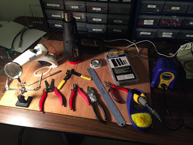
Tools
- soldering iron and solder
- wire strippers
- flush cut wire cutters
- 1/4" and 5/16" heat shrink tubing
- hot air gun or candle
- hot glue gun
- sandpaper
About Piezo Elements (Benders)
A piezo element is a metal disk with a circle of piezoelectric crystals in the middle. When the crystals are made to vibrate, they produce an oscillating voltage. Conversely, if you apply an oscillating voltage to a piezo element, it vibrates--that's why they also work as buzzer elements. A piezo element has 2 terminals: the inner circle which is the signal terminal and the metal disk which is ground. A good discussion of piezo elements and how they work can be found at Open Music Labs.
About Balanced Microphone Cables

Since a piezo has 2 terminals, we need a cable with 2 conductors to connect to it. You might think that simple speaker wire would do, but there's another consideration--cables can act as antennas that pick up stray electrical signals in the environment that can cause audible hum when plugged into an amp. To counteract this, you need to use shielded cables that have a sheath of wire surrounding the conductors. Shields are typically made of thin copper wire that is either wound in a spiral or braided around the conductors. (Foil shields are also used for cables that a part of permanent installations, but are not appropriate for this project.) Audio technicians typically agree that the highest quality (and most expensive) mic cables use braided shields, but spiral wound shields are perfectly fine for this project, and are somewhat easier to work with. In addition to the 2 conductors and the shield, mic cables may also have "filler" that helps the cable maintain its round shape. This filler may be plastic lines or bundles of thread, as pictured above. It doesn't matter which type you use for this project--if your cable has filler in it, you'll just need to snip it off before soldering your connections. You can buy bulk microphone cable from online suppliers such as Redco or Parts Express, or else you can just buy a mic cable from your local music store and just cut it. Do not use guitar cable for this project--it has a very different arrangement of a single conductor surrounded by a shield which is not appropriate for connecting to a contact mic in the manner we suggest.
Step 2: Strip Cable End for Jack


- Start with an 8" length of mic cable.
- Carefully strip around a half inch of the plastic or rubber cable housing from one end using a sharp hobby knife or an adjustable wire stripper. (Strip just enough to be able to make connections to the jack.) Be careful not to cut the wires or shield inside--just slowly score the housing until it splits and then pull it off.
- Separate the copper shield wires into a bundle. If there is filler, snip it off (be careful not to cut the wires!)
- In a typical mic cable, one of the insulated conductor wires is either blue or red and the other is clear. We'll use the clear wire as ground. Strip the ground wire down to as close to the edge of the cable housing as you can and twist the wire together with the shield.
- Strip off around 1/8" inch from the end of the signal wire and twist it into a bundle.
- Bend the stripped end of the signal wire 90 degrees, to create a little tab that we will insert into the signal terminal of the jack.
Step 3: Solder Leads to Jack

The jack has two terminals: a signal terminal that goes to the tip of a plug and a shield terminal that goes to the grounded plug housing and the cable shield. The signal terminal is usually a metal tab connected to the body of the jack with a small hole in it. Some jacks may have two signal tabs. If the jack is a mono jack, then you may connect the signal to either one of these. The shield terminal is usually a long strip of metal that may have a folded tab that forms a "pocket" for connecting the ground wires, or there may be a small hole in the bottom of the strip. The figure above is of the pocket variety.
If you plan to do a lot of soldering, it's worth investing in a good iron, as well as a good set of strippers and wire cutters. I use a temperature controlled iron set at 700 degrees with a chisel tip. This transfers a lot of heat quickly and melts the solder fast, which I prefer. There are a number of good Instructables on how to solder.
Before you connect the wire leads to the terminals of the jack, you should "tin" the wires by applying a small amount of solder to the wires. I use a cheap "helping hand" tool with alligator clips to hold my work while I solder.

After you've tinned the wires, put a small blob of solder in the "pocket" of the lead terminal. You should touch the soldering iron to the inside of the pocket to heat it up and then slowly feed the solder into the point where the tip of the iron and the pocket terminal meet.
Now we're ready to connect the wires. Fit the angled end of the signal wire through the hole in the signal terminal and solder it into place with a small amount of solder. Next, slide the ground wire up into the pocket and solder it into place. Use flush wire cutters to cut the wire ends off flush with the terminals. Using pliers, crimp the tabs on the end of the ground terminal to grab the cable housing. When you're done, it should look like this:

Note that there is little excess solder and there is clean separation between the signal and ground connections. It's worth taking your time to get a clean result.
Here's an example of a plug that has a small hole instead of a pocket for the ground wire. To connect the ground wire, simply bend it down to fit through the hole. Note that a large bundle of wire won't typically fit through the hole. To get a smaller bundle snip of half of the shield wire before you twist the shield to the ground lead wire.


Step 4: Heat Shrink Tubing Over Jack Connections


Heat shrink tubing over the jack connections serves 3 purposes:
- It protects the signal connections from shorting to the grounded shield housing
- It adds mechanical strength to the connection
- It reinforces the place where the cable enters the jack, to keep it from breaking from too much flexing. (You know how annoying it is when the cord on your phone charger wears out at the joint!)
- Cut a 2" length of 5/16" diameter heat shrink tubing and slide it over the jack terminals as shown
- Turn the tubing slowly over a heat gun or candle until it shrinks
- If the jack came with a plastic jacket, slide that over the shrunk tubing.
- Screw on the housing.
Step 5: Prepare the Cable End for the Piezo


- Strip off a length of cable housing that's the same as the diameter of the piezo, a little more than an inch.
- Completely trim off the shield wires and any filler material
- Strip 1/8" inch of insulation off the ground wire and fold it over 90 degrees
- Trim the signal wire to a length near the middle of the inner circle crystal contact and strip off 1/8" of insculation
- Tin the ends of the wires with solder--be generous with the amount of solder
- Shrink on a short length of 1/4" diameter heat shrink tubing (around 3/8") over the cut end of the cable housing. This is to prevent any stray fringe wires ends from the copper shield from touching the the crystal contact when we solder the leads in place.
Step 6: Solder the Leads to the Piezo


- Melt a small blob of solder near the perimeter of the metal ground disk. To do so, first hold the iron to the disk and then feed a little bit of solder to the point where the iron and the disk meet. Be careful no to let the solder short to the inner crystal circle.
- Hold the end of the ground lead on the solder blob and touch the lead and the blob with the soldering iron until the solder melts and forms a joint.
- Solder the signal lead to the crystal terminal. If the wire lead doesn't sit nicely against the terminal, it may help to melt a little blob of solder onto the crystal terminal like you did for ground, and then solder the lead to the blob.
Step 7: Test the Microphone

Plug the mic into an amp using a guitar cable. Test it by tapping on it.
Step 8: Mount in Bottle Cap

Cut a notch into a standard 20 oz drink bottle cap that is big enough for the cable to fit loosely. I do this by first drilling a 1/4" hole on a drill press (hold the cap with pliers or vice grips while drilling), cutting away the excess with wire clippers, and then using a Dremel or file to enlarge. Sand off the nubs from where the bottle cap attached to the ring on the bottle neck.

Apply hot glue over the solder joints and along the joint between the cable and piezo

Apply a generous ring of hot glue around the inside edge of the bottle cap. The glue should come right up to the rim of the cap. Watch your fingers--hot glue is hot!

Set the piezo and cable assembly into the bottle cap so that it is uniformly flush with the rim and hold in place until the glue is firm. It's important that you get it as close to flush as possible, so that the piezo will make good contact with a surface. Apply a ring of hot glue around the joint between the cap and the cable.

Dip the bottle cap and piezo into Plast-Dip just past the joint. Be sure to stir the Plasti-Dip well before you do the dipping! When you dip, lower the mic slowly (take a few seconds) and then remove slowly. Hang the mic by the jack, remove drips with a paper towel, and let dry for a few hours. 
You're done!
Step 9: Compose and Play Some Music!
In this Instructable, Peter Martin of Third Coast Percussion provides tips on composing and playing percussion music.
Step 10: Using the Contact Mic As a Guitar Pickup

You can use this contact mic as a pickup for an acoustic instrument such as a guitar. If you do, you'll probably want to use a longer cable than 8", so that the jack clears the top. To attach the contact mic to the guitar, use a little bit of poster mounting putty. You can further secure the mic and cable using gaffer tape, which holds well but doesn't leave a residue when you remove it. You can experiment on where to place the mic to get the best sound, but just below the bridge on the side of the high strings works pretty well.
One issue with using a piezo contact mic as a guitar pickup, is that if you connect it directly to a typical guitar amplifier, some of the bass gets filtered out. Using a preamplifier with a high input impedance can correct this problem. I've written this Instructable on making a Guitar Contact Microphone Preamplifier as a solution to this problem. It's a simple design that fits inside of a mint tin, and also includes some basic explanation on how the preamplifier works.


