

Introduction: Make a Desktop Tamagotchi


One day I was sitting behind my desk at work and I got that weird need to build something, after looking around for a bit I got my eye on an LED matrix and that sparked an idea in my head : "I WANNA MAKE A TAMAGOTCHI".
So for those of you that don't know what the heck is a Tamagotchi here is a little snip-it from wikipedia :
"The Tamagotchi (たまごっち Tamagocchi?) is a handheld digital pet, created in Japan by Akihiro Yokoi of WiZ and Aki Maita of Bandai. It was first sold by Bandai in 1996 in Japan."
So my take on this classic toy is to make it in to a desktop gadget with an LED matrix for a display, and an Arduino for brains to make it more accessible to people. With that said join me as we design,build and program the World's first (As far as I know) desktop Tamagotchi.
Step 1: Getting the Right Stuff


So like any other electronics project you will need to get some basic tools:
1) Soldering Iron
2) Some solder wire
3) A pair of cutters
4) A pair of needle nose pliers
Optional : Get some solder braid or a solder pump to fix soldering mistakes
As for the electronics the parts list a bit longer, here is what you will need to get:
1) An ATmega328P with the arduino bootloader + 16Mhz crystal with two 22pF caps
* You will need something to program the chip as well like an arduino platform or an FDTI adapter
2) 4 x 74HC595 shift registers
3) 2 x ULN2803 Darlington transistor array
4) 1 x DS1302 RTC + 32.768kHz Crystal
5) 1 x 3V coin cell battery holder + the battery.
6) 4 x right angled push buttons
7) 1 x Peizzo Buzzer
8) 4 x 8x8 LED matrix modules
9) 16 x 330Ohm resistors (you will need to calculate the value for your matrix)
10) 2 x row of 16 female pin headers
11) 2 x row of 16 male pin headers
12) 1 x row of 4 female headers(For programming)
13) 5 x 100nF cap
14) 1 x 10uF cap
15) 1 x 10K resistor
15) Power jack connector
16) 5V DC wall wart
17) A big piece of protoboard
18) Some wires for connections
Step 2: The Hardware Side


Even if this project if mostly software focused we will need to build the hardware first to make life writing code and debugging it easier.
The hardware consists of 2 main parts: The microcontroller part and the LED display.
The microcontroller part is very straight forward, it's an standalone arduino(ATmega328 with the arduino bootloader) with
some peripherals(4 buttons, a buzzer and an RTC), but the it's the most critical part as it does all of the thinking.
The LED display part is a bit more complex and takes some time to solder up. This circuit consists of 4 shift registers (74HC595),
2 darlington transistors arrays (ULN2803) and 4 8x8 LED matrices.
Like most LED displays it comes as no surprise that the display need to be multiplexed(look it up it's a pretty cool concept) because driving 16x16 LEDs individually will take 256 pins from the microcontroller and that's just silly.
Even with the multiplexing approach we will still need 32(16 rows + 16 columns) pins from the microcontroller to drive the display which again we don't have, so the solution is to use shift registers as an I/O expansion , 4 8 bit shift registers give us 32 outputs and it only takes 3 lines to control them all.
But the problems don't end here because the shift registers can't handle sinking the current of 16 LEDs (if a full row is lit) on one pin so we need to give it a hand with the help of the darlington transistor array that will act like a buffer that can handle big currents which can fry the shift registers.
So to recap we use 4 daisy chained shift registers to control the display, the first 2 drive the rows and the other 2 drive the columns with the help of the darlington array.
The only thing that needs to be calculated in this project is the value of the resistors that will drive the LED rows.
The formula is very simple and goes like so :
R = (Vsource - Vled)/ Iled
Vsource is 5V, Vled is the forward voltage on a single LED in the matrix and Iled is the forward current of that same LED.
You can also use online calculators to help you with this.
Step 3: The Construction Concept - LED Board


When I started the build I wanted to get a clean look without using a case (finding the right case is a nightmare) so I went for
a two piece construction i.e. one board that holds the LED matrix and the second one with all of the electronics.
This way the only thing you see when you're looking at the front is the LED display itself and all of the other stuff is hidden behind the display.
The first board with the LED matrix will dictate the size of the second one because you want to hide the other board behind the display. So place the matrix assembly on the board, mark where to cut and cut the board. Cut the second board so it will be the same size as the first one. The trick with this building style is to have to proto-boards of the same size, so it's a good idea to sand the boards to get them to the same size.
Because I had 4 8x8 LED matrices I had to connect them together to get one 16x16 LED matrix, that's quite simple and take just a bit of time to connect them together. The way you do it is by connecting the rows of the horizontal matrices with on and other and connecting the columns of the vertical matrices (I made the connections with some thin wire-wrapping wires).
Now the only part that is left with this board is connecting the headers that will connect the to boards together, the placement of this connector is decided by the position of the switches on the second board. The switches will be on the sides of the board so you can't put the connectors on the edge of the board that's why the connectors are placed about 4 holes from the edge.
There are two connectors one for the rows and the other for the columns.
And to finish the look I recommend putting a sheet of white paper over the matrix to hide the assembly and get a clean look.
I glued the paper to the edges of the matrix so the display is safe from the glue.
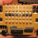
Step 4: The Construction Concept - Driver Board


Now the driver board is the most complex part of this build because of the space constrains and I can't really tell you how to build it because every one has its on building style.
What I can tell you about is the placement of the key components like the buttons and the connectors. Now the buttons should be at the sides of the board and most be right angled so that they will be out of sight but you could still press them.
From there you place the connectors that will join the two boards, the connectors should be as close to the edge as possible to give a good and sturdy connection, that is way you place the buttons first at the edge and from there you decide where to put the connectors.
note:It's pretty important to make sure that the connectors on both board join together perfectly and the sides of the boards are flush.
After those critical parts done you are free to build the rest as you see right, but make sure that there are no parts that go "overboard".
I will recommend build in groups and keeping all the parts in that group close to each other for ease of wiring for example:
The column connector should be connected to the two darlington chips and the two shift registers so it makes sense to put that bunch close to each other and with a bit of thinking it's possible to get away with only a few wires here and there in this group.
Also make sure to put some programming headers for the micro-controller for future mods.
Step 5: Game Rules

After finishing the hardware part it's time thinking about the code and the game mechanics.
This was the hardest part for me because I stared from scratch and had to make up my own rules which aren't perfect by any means.
The game as it is, is very easy to exploit and to do well in but this isn't a serious game and it's meant to be a cool little gadget.
So with this little disclaimer out of the way lets talk a bit about the game rules.
The pet has 5 basic stats: health, weight, happiness, hunger and age.
The players role is to balance this stats by 4 actions he has: feed the pet,play with him,clean after him and medical care.
Each action has a positive effect and a negative effect and the player needs to make an effort to choose the best compromise.
When the player chooses to feed the pet he has 3 options: give him a meat meal, give him a fruit or a candy treat.
A meat meal makes up for the most hunger points and adds lots to the weight, a fruit raises the pets health but lowers the pets happiness and the candy gives a big happiness boost but lowers the health and raises the pets weight.
When the player chooses to play with the pet a Simon games starts and depending on how good the player did the happiness stat raises, but if the player did very badly the happiness will go down.
From time to time the pet will go to the toilet and the player needs to clean after him, each turn the player miss lowers the pets health and raises the chance to make the pet sick.
Also there is a random chance that the pet will get sick, that chance is higher if the pet is old or dirty. There are 3 levels of sickness each with it's own negative effects. The player can give a shot to the pet to cure him but this will lower the pets health (no one like taking shots :D ).
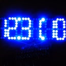
And the most impotent part (for me) is that the pet goes automatically to sleep at 23:00 and wakes up at 8:00 so that it will not die over night. Of course you can change this part for your liking and set a new bedtime for the pet.
Step 6: Software: Menus and Animations


Here we are at the most time consuming part in the project, after deciding on all of the features and states of the game it's time bring them to life by creating all of the animations, settings,actions and states of the game.
For this step I used a combination of two programs : paint.net and excel.
In paint I created all of the icons and menu screens one by one. Using paint is a great help because you can easily copy,paint ,delete and manipulate the image. Never the less this part was super hard for me because I had hard time coming up with custom icons that stand up for each action,setting,food and emotions.
Note: In paint I used the pixel grid option to allowed me easily to divide a section in to pixels and paint each one.
After finishing that work on the animations and icons I numbered the icons in groups and started working on creating the bitmap of the icons, to do so I used my favorite trick in excel to create the bitmap.
I have created an excel spreadsheet that allows me to "paint" with cells in a specific area and then it spits out the bitmap in the format I want.
After this all is done it's just a matter of coping the bitmaps in to the code and starting writing the software.
Attachments

Step 7: Software: Final Code

The main part of this project is the software and it's the thing that gives this project it's character.
Now I will not go over the code in detail here because I have done that in the code itself so expect to see lots of comments there(some with some horrible spelling mistakes :D).
The code uses 3 libraries but they all come with the Arduino IDE so there is no need to download any.
I wrote the code without any special libraries to save the trouble of keeping the code up to date and finding those libraries in the future,
this is why the code is long and has lot's if different functions.
Now the code it self has two main parts: the main loop which handles all of the game rules and the "pets" behavior and a timer interrupt routine which handles the display updating.
My work on the code is still not finished because there is always new things to add and improve in it, so I will updating the code from time to time. But for now the code is in it's working state and fully featured.
Attachments
Step 8: You're Done! What Next?

Yay! We are done! or do we?
We have a fully working bench top Tamagotchi with all of the basic functions but why stop there?
There are lots of things to add and improve upon and it's up to you to do so. So take the hurdles and improve, change and have fun with it!
And not forget to put in on your deck with pride and show off your new creation.
P.S.
Take good care of it and don't forget to feed it from time to time :)

Participated in the
Arduino Contest


