

Introduction: Make an Arduino Controlled Motorized Camera Slider!


This project shows you how to convert any ordinary slider to an Arduino controlled motorized slider. The slider can move very fast at 6m/min, but also incredibly slow.
I reccomend you watch the video to get a good introduction.
Things you need:
- Any Camera Slider. I used this one.
- An Arduino Micro
- 4 Small Toggle Switches
- A 12Volt Battery Pack
- A timing belt and 2 pulley
- A stepped Dril bit
- A soldering Iron. I can totally reccomend this one. It is an investment, but it pays out in the long run.
- A4988 Stepper Driver. In theory you only need one, but its easier to troubleshoot if you have multiple. They are cheap anyway.
- A 12V stepper motor
- A center punch
- A metal saw or angle grinder
A drill press or handheld drill
Step 1: Drill the Mounting Holes for the Stepper Motor.


The stepper motor needs to be mounted underneath the track. The closer to the end, the longer your length of travel. The easiest way to transfer the hole pattern from the motor to the track is by tracing it with painters paint. This is a very useful tip for all kinds of applications.
The pulleys were quite high, so I had to drill large holes to accomondate for some of their height inside the track. That can be easily done with a drillpress and a stepped drill bit.
Make sure you use a center punch to mark the locations of the holes. This makes drilling them easier and more precise.
A 90° chamfer bit cleans up the edges nicely.
Step 2: Mount the Motor on the Track.


Nema 17 motors useually have 3mm threaded holes at the top. I used some washers to reach the perfect hight for the belt. The belt needs to ride quite low in the track to clear the carriage.
The pulleys are fixed to the shaft with a set screw.
On my slider the holes collided a little bit with the round surfaces of the track. I had to do some filing to get the screws in propperly. If you plan ahead and twist the motor a few degrees it should be alright. Two screws are enough anyway though.
Step 3: Making a Little Mount for the Idler Pulley.


The idler pulley, just like the stepper pulley, needs to be mounted slightly below the surface of the track. I used a little piece of metal that I had left from a previous project. You will find something similar in any hardware store.
I used countersunk screws. They look awesome, but only when they are propperly seated inside their holes. To achieve that, I started with one hole, inserted the screw and then drilled the second one. That ensures a perfect fit. A chamfering bit is used to create the counter sink.
For an extra nice look you should paint the metal. Using primer is always a good idea. Mine did not work very well at -10C°.
Step 4: Assembly the Idler Pulley!


The idler pulley needs to be at the same height as the motor pulley. I used washers for that. I strongly reccomend using nylock nuts! They have a little plastic insert that bind with the thread and stop it from becoming loose by the vibrations.
Step 5: Modify the Carriage to Hold the Ends of the Timing Belt.


Your belts will likeley come as a 5m length which you can be cut to size. That means that both ends need to be fixed to the carriage.
I tried a few methods of attaching them to the carriage before I found a very simple solution. I just wedged the belt against a parallel surface using a countersunk M3 screw. I drilled a number of holes to make sure that one would have the right distance to hold the belt tight.
Step 6: Admire Your Hardware!

By now you should have a belt that is connected to the carriage and that loops around the motor and the idler pulley. Next come the electronics!
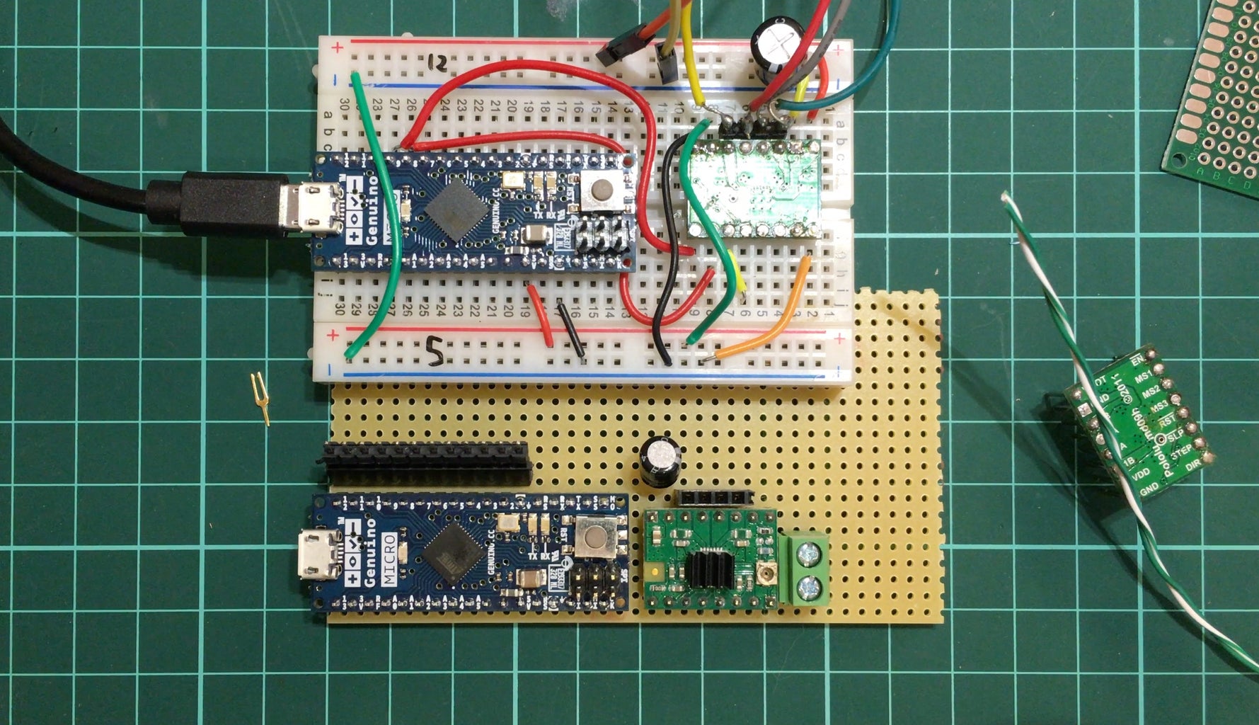
Step 7: Electronics Overview

I am using an Arduino Micro. This is a great little device with a small form factor and a lot of support material online. The arduino is powered by a 12V battery pack consisting of 8 AA batteries. I find this more convenient than using a LiPo. The battery pack is also directly wired to the Stepper driver since it needs a higher motor controll voltage and current than the Arduino can deliver. The stepper driver gets signals from the Arduino over 2 cables and it controlls the motor. The Arduino starts giving directions to the driver as soon as it gets power. 4 switches are used as some kind of combination lock to set the speed of the motion.
Here is the Code. Unfortunatly the circuits.io code got deleted when the website was sold. The code below works fine.
Step 8: Wiring the Switches to the Arduino


Unfortunatly the shematic was lost because circuits.io got deleted. How can I explain the shematic best? The Arduino is usind the 12V battery pack as a voltage source. It produces a 5V voltage itself that can be used to check the state of the 4 switches. They are used to change the speed of the slider. So you kinda have 2 voltages on the board. 12V to power stuff and 5V for the controll circuit.You need to connect your 12V source to the Vin and GND of the Arduino. Vin stands for voltage in. That part is easy.
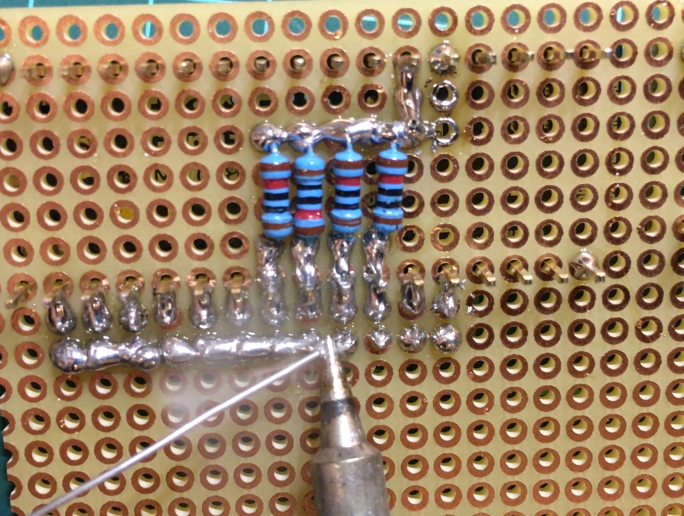
Then you need to add the 4 switches. For that you can use the shematic used here and copy it 4 times for the 4 switches. Sorry that the real shematic got lost. Use the pin2 to pin5 that you also find in the code below. Do not use pin 1, that doesnt work. What are the resistors for? Well an Arduino cannot meassure current, but it can measure voltage. So the toggle switch either connects 5v to the pin, or it lets it short to GND. The resistor just before GND is there to hold the voltage near zero. You need individual 10k resistors for each switch! If you follow the tutorial above, which is quite simple and one of the basics of Arduino, the Arduino will constantly check the current state of the switches and react accordingly. I hope this helps.
Once this circuit works, you can transfer it over to a breadboard and solder it on.
Wire some thin cables to the 4 switches. I used the cables I found inside an old ethernet cable. I am sure you have plenty of those lying around. Protect the bare terminals with shrink tubing.
You should now have 4 switches connected to an Arduino and the Arduino should run and register that those switches are pressed.
Step 9: Wiring the A4988 Stepper Driver


The stepper driver is an A4988. It receives signals from the Arduino and relays them to the Stepper. You need this part.
Instead of explaining the circuit to you, you can rather watch this tutorial as it explains it very well. This is my go to reference whenever I use an A4988. My code uses exactly the same pins. So add this youtubers tutorial to the board with the switches from the previous step and it will work.
Step 10: Add the Code!


Here is the entire code and the circuit for the slider. You can test it online, but only without the stepper driver.
Alternative Link
The code checks for the state of the 4 switches in the loop. After that it goes through some if statements and selects the desired delay between the steps to move through the entire length of the slider in the entered value. All the calculations are included in the code as notes.
You need to enter the length of your slider and the diamter of the pulley to ensure that the motor stops when it reaches the end of travel. Just measure those values yourself. The formulas are included in the code.
The table shows you what switches to press for a desired time period. For instance if you want the slider to move the entire length in 2min you need to activate switch 1 and 2. You can of course change these values to your preferences.
Step 11: Print the Enclosure.


I designed the enclosure using Fusion 360. You can download the files here and print them on a 3D printer. No support is required. I filled the details of the letters with pink nail polish to make it easier to read. You can fill the entire letter and then wipe away the access. This trick can be used for all kinds of indents.
If you want an easier option, you could just make one by hand using a small lunch box.
Step 12: Final Assembly


Its time to put everything together. Place all the components inside the enclosure and mount it to the slider using double sided foam tape. This stuff is pretty strong and nicely adheres to uneven surfaces.
I also added an anti vibration mount with a universal camera mount on top. The vibration mount is fairly cheap and stops vibrations to reach the camera. This is only needed for high speed motion. In my case high speed motion is anything between 10s and 30s for the length of the slider.
I added a table with all the switch combinations on the underside.
Step 13: Admire Your Work and Shoot Some Cool Footage!

Weather its video or timelapse, this slider can do it all! If you build one yourself I would love to find out about it!

Runner Up in the
Microcontroller Contest 2017


