

Introduction: Make Your Own PCBs on an Inexpensive Desktop CNC Mill


Traditionally, there are two ways of hobbyists making custom PCBs:
1. Using toner transfer and chemical etchant -- can be tricky to get the right materials, and the chemicals are nasty and messy
2. Paying a service like BatchPCB or OshPark -- fairly inexpensive, but usually have to wait a long time, like two or three weeks.
Milling them on a CNC is a quick way with a different set of pros and cons:
The good:
* Quick turnaround - don't have to wait days or weeks for it to ship
* The mill does the drilling
* No messy acid to deal with
* Once you have good settings, the process is easily repeatable
* Two sided boards are possibly slightly easier than with etched boards
* Inexpensive - you're just paying for blank circuit boards which are a couple bucks each
The not so good:
* Bits and end mills can be expensive and they wear out.
* Bits of copper clad fiberglass get all over the place
* Milling a board can take a while
* Board stock and mill bed flatness will present a challenge
* Isolation size is a function of bit size and mill accuracy. Check your design carefully before you plan on using fancy SMT parts with densely packed pins.
How I've Made Things Work:
I'm a CNC newb and an electrical engineering disaster so my milling process and the following outline use what I've determined to be the most common (though not necessarily the best) tools.
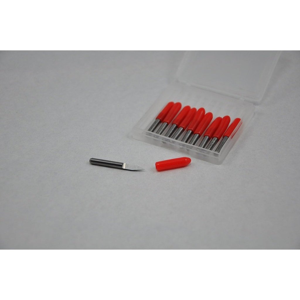
Those tools are Eagle CAD, pcb-gcode, pcb-probe, Mach 3 CNC, Zen Toolworks 30deg V Shaped Engraving Bit, random surplus carbide PCB drill bits and, of course, Guido for doing the milling. If you want to get those tools, see the links below.
The only tricky part is related to the V shaped bit. Obviously, you will want to etch the smallest, cleanest line that you can in order to mount all of those tiny surface mount LEDs that you already bought. Unfortunately, the V shape of the bit will change the width of your cut depending on how deep you cut into the board. Since your copper clad stock isn't perfectly flat you are challenged to pick a milling depth that will cut clean traces across the entire board.
I've had some success with flattening my copper clad as much as I can by using a metal straight edge to check flatness and then bending the board by hand to try to make it flatter. With the board then as close to flat as I can make it, I would then test at what depth I can cleanly etch a line on all four areas of the board that surround the area that I plan to etch. The results were always usable but I sometimes found myself rebuilding missing traces with bits of jumper wire.
A better way seems to be to use some G-Code trickery to probe the height of the board at key points on the surface and then perturb the height of the vertices accordingly while milling. It sounds both awesome and complicated but luckily for you there is already a program that does all of the work so you can just deal with the awesome part and follow along with my directions.
Submitted by Ace Monster Toys Hackerspace in Oakland, CA for the Instructables Sponsorship Program.
Check out the original version on our wiki -- it's somewhat specific to our particular machine, I've tried to write this instructable to be more generic and widely applicable.
Step 1: Requirements


The Hardware
I'm using a Zen Toolworks CNC mill, with Mach3 on Windows driving the machine. It should be easy to follow these instructions on any mill that is similar, and in theory with a little work you should be able to translate them to any CNC.
Bits and End Mills
* Zen Toolworks v-shaped engraving bit (amazon) (Zen Toolworks)
* Slightly used carbide drills (Electronics Goldmine)
Blank Circuit Boards
* Look for "copper clad" boards. Radioshack sells a small doublesided one for $4.50.
The Software
* Eagle CAD - download the free version of Eagle CAD from cadsoft.
* pcb-gcode - download the pcb-gcode Eagle CAD plugin (Local Mirror)
* pcb-probe (with mach3 support) - get the source code from github (Local Mirror) (pre-compiled for windows)
* OPTIONAL: pcb2gcode - I've never used this. It makes G-Code from gerber files instead of from Eagle CAD. Check out Sourceforge.net and Github
Step 2: Designing a Board With Eagle

Board design is well out of scope of this document but Sparkfun.com has kindly provided these tutorials for using Eagle CAD to make circuit board designs.
Use Eagle CAD DRC to Enforce Design Limitations
1. In Eagle CAD, select 'Tools->DRC->Clearance'
2. Set all of the 'Different Signals' clearances to a value larger than your engraving tool (12mil seems to work for a Zen Toolworks 30deg V-Bit)
3. If you already have a board designed, select 'Check' to see what parts of your board may be too close together to isolate
Step 3: Make G-Code for a Board
Use pcb-gcode to generate G-Code from Eagle CAD
1. Open your board design in Eagle CAD
2. From the Eagle CAD Control Panel window, right-click User Language Programs->pcb-gcode->pcb-gcode-setup.ulp and select 'Run In Board'
3. The pcb-gcode dialog will pop up.
4. On the 'Generation Options' tab, select 'Generate bottom outlines', 'Generate bottom drills' and 'Show preview'.
5. For 'Etching Tool Size' enter 0.254mm
6. On the 'Machine' tab, set 'Spindle Up Time' to 3 and set the feed rates to 300mm/min
7. Set 'Z High' to 12mm, 'Z Up' to 3mm, 'Z Down' to -0.08mm
8. Use calipers to determine the thickness of your board and enter that value plus .1mm or so for 'Drill Depth'
9. On the 'GCode Style' tab, select 'Mach3 - EMC for Windows'
10. On the 'GCode Options' tab, select all of the 'NC File Comments' options as well as 'Do tool change with zero step'
11. Click 'Accept and make my board'
12. An image view window will pop up and display what will be etched. pcb-gcode will join signals that are too close so look at the image carefully to make sure that all signals are properly isolated.
Use pcb-probe to generate leveling G-Code for your board G-Code
13. From your favorite command shell, navigate to the directory where your Eagle CAD board files are saved.
14. Look for some files that end with '.tap'. Those are the G-Code files you generated with pcb-gcode
15. Find a file named (something).etch.tap. That is the G-Code for etching your design.
16. Run pcb-probe on that file by typing 'pcb-probe (something).etch.tap (something).probe.tap
17. You should see something like this:
Processing input file ... pov_driver.bot.etch.tap
Board Size (mm): 47.5488x32.3088
Generating Mach3 GCode output in pov_driver.bot.probe.tap
Done.
18. Copy your (something).probe.tap file onto a USB disk to load the file onto the Mach3 machine that drives your CNC
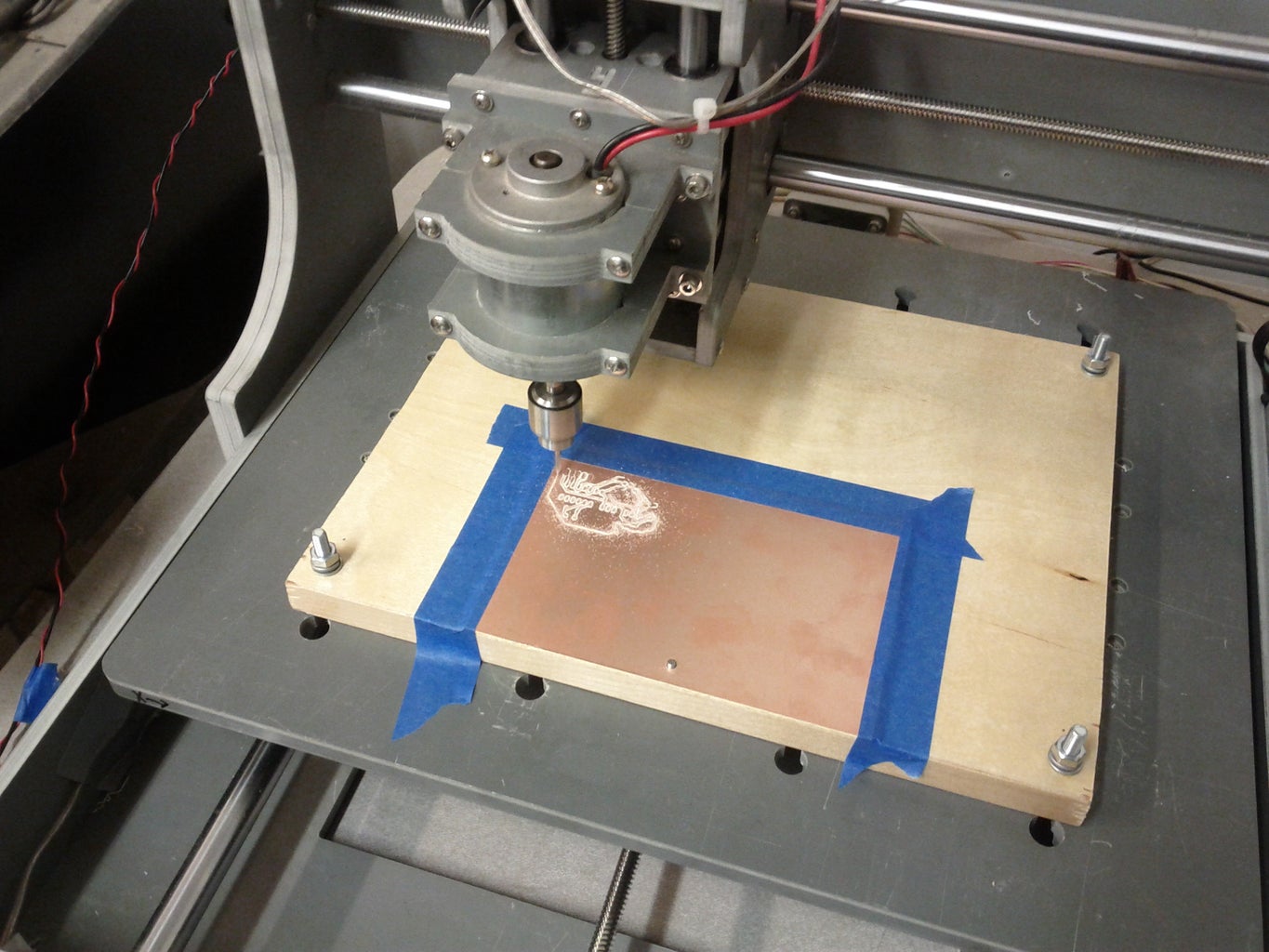
Step 4: Hold Down Copper Clad Stock on CNC's Spoil Board


1. Drill a 1/8" hole near an edge of your copper clad stock
2. Clean your copper clad stock with a mild abrasive such as a scotchbrite (aka green scrubby) pad
3. Put the pin on the spoil board through the hole of your copper clad
4. If you are making a two sided board, take care to line up the edge of your copper clad so it is parallel with the edge of the spoil board.
5. Tape down the edges of the copper clad. (Blue painter's tape works great. Please don't use duct tape--it makes a mess).
Step 5: Get Ready to Probe for Surface Height

1. Chuck the end mill you plan to etch with into the spindle
2. Find the black and red wires dangling off of the IO board
3. As tightly as possible, tape the black wire to your copper clad board
4. Use an alligator clip to connect the red wire to the the spindle
5. Within Mach3, select the 'Diagnostics' tab.
6. Click the flashing 'Reset' button so that the motors are enabled.
7. Use the arrow keys and page up/page down to jog the spindle so that the end mill just touches the surface of the copper clad.
8. When the end mill touches the surface, you should notice the green input indicator next to the word 'Digitize' light up on the Diagnostics screen.
9. If the indicator does not light up, check all of your connections and make sure your copper clad board is clean.
Step 6: Load G-Code and Zero the Mill and Probe
1. Select the 'Program Run' tab in Mach3
2. Plug your USB Drive into the Mach3 PC and use 'File->Load GCode' within Mach3 to load your file.
3. Use the arrow keys to jog the spindle to what will be the lower right corner of your etching. Leave some extra room to avoid disasters.
4. Click 'Zero X', 'Zero Y' and 'Zero Z' on the Mach3 Screen
5. Click 'Cycle Start' on the Mach3 Screen
6. When prompted, jog the spindle down to within 5mm of the board and click 'Cycle Start' again.
7. The CNC will begin probing the work piece. If at any point Guido seems to be plunging the bit into the copper, hit the red E-Stop button and check your connections.
8. If you need to fix a connection and restart the process, be sure to use the 'Rewind' button in Mach3 before clicking 'Cycle Start' again.
Step 7: Engrave!

1. When prompted, disconnect the probe wires and move them out of the way.
2. Make sure you are wearing eye protection
3. Enable the spindle
4. Click 'Cycle Start' on the Mach3 Screen to begin engraving
5. Use the spindle speed control to adjust the spindle speed to something appropriate. If the speed is too low you may see ragged chips of copper. If the speed is too high you may see copper being finely polished instead of cut.
Step 8: Drill!
1. When engraving has finished, use the page up/page down keys to raise the spindle.
2. Click 'Go To Zero' on the Mach3 Program Run tab
3. Use the page up key to raise the spindle again
4. Remove the engraving bit from the spindle
5. Chuck an appropriately small carbide tipped drill bit
6. Use 'File->Load GCode' within Mach3 to load your drilling G-Code (named something like something.bot.drill.tap)
7. Use the page down key to lower the spindle until it is just barely touching the work piece
8. Click 'Zero Z' on Mach3
9. Click 'Cycle Start' on Mach3 to begin drilling
Step 9: Milling!

After you've engraved your circuit you need to cut it out from the copper clad stock somehow. So far I've done this by scoring and snapping the copper clad, cutting out the board with a 40tpi blade in a jigsaw, using a paper cutter and using hand written G-Code for the CNC to mill out the board.
Using the CNC and the jigsaw are both very messy but since our CNC can be easily connected to our dust collector I'm inclined to automate the gcode creation and focus on that method. Until then, using a paper cutter works surprisingly well if you don't mind cutting all the way across your stock every time and having your cuts be imprecise.
Step 10: Things That Will Go Wrong
- When the tip of your V shaped end mill is worn or broken, the CNC will cut wider isolation routes than you programmed pcb-gcode for.
- When the V shaped end mill is dull, the CNC will need a lower Z height in order to cut at all.
- pcb-gcode will silently connect signals if they are too close to be isolated with the tool you have specified.
- Whenever possible, use wide traces in your board design so that sloppy milling isn't a problem.
- When in doubt, use a new end mill.
- Pay attention to Eagle's DRC to make sure that your signals can be isolated.
Step 11: TLDR: What Not to Do
- Don't drop the bits. They will break.
- Don't crash the tool. I know you're going to crash the tool because you don't know what you're doing, so remember not to crash the tool and you'll feel bad when you crash the tool and probably won't do it again. Just raise the spindle before you go crazy hitting return to zero and if you stop a program don't just restart it somewhere in the middle and expect everything to be OK.
- Don't forget to wear eye protection. Guido is a robot that cuts things and it's not sophisticated enough to follow Asimov's laws about not hurling bits of metal into your eye.
- Don't start and stop the PC with the spindle turned on. That thing is just hooked up to a pin on the parallel port and that pin gets mercilessly diddled by legacy windows upnp probing which may surprise and/or hurt you by running the spindle. Just turn it off.
- Don't leave the mill running unattended. You need to be there to hit the pretty red e-stop button when something horrible happens.
- Don't leave a mess for the next person. That shop vac, broom and dustpan is there for you, not your mom.


