

Introduction: Making Stencil for Soldering Using Silhouette Cameo, or How to Convert Bitmap (bmp, Jpg, Pdf, Etc.) to Vector (svg or Dxf) Format.


These two formats are more common. The .DXF is popular with computer aided design software like Autocad. Scaleable Vector Graphic, svg, files are XML-based vector graphics that can be exchanged between various 2D software.
Both of these formats are vector based images formats. That means they are based on lines and not individual pixels for information. These lines translate into the cutting path the Silhouette cutter follows.
The problem is a lot of images start as a JPEG, PDF, bitmap or other format style. These are not vector images and cannot be used by Silhouette directly. They have to be converted.
Step 1: Get the Software Free of Charge
Adobe Photoshop can create paths based on an image, and then the paths can be exported to Illustrator. Inkscape may be another possible option for the conversion, but I could not get the software to work. All my instructions are based on Photoshop and Illustrator.
What if you do not own Photoshop? Adobe has discontinued operating their software activation server for the old version of CS2. http://www.forbes.com/sites/adriankingsleyhughes/2013/01/07/download-adobe-cs2-applications-for-free/This includes both Photoshop and Illustrator. Adobe has posted the software key for users to download. The big limitation is it will not run on the latest computer hardware with the newest operating system.
Technically, Adobe is not giving away the software for free, but they are not selling this version any more. If you want to use the software and the key is posted on their website, I’m not sure what you would call this kind of offer. They have made it easy to you to get this “obsolete”, and unsupported version of the software for no cost.
Step 2: Save Your PCB As PDF
Our interest in this is to convert PCB board layouts into stencils for soldering. We start the process in EagleCAD. Follow our Instructable https://www.instructables.com/id/Making-Paper-Soldering-Stencils-for-Electronic-Cir/ on how to export your Eaglecad files to pdf. Once the image is a pdf, then open it in Photoshop.
Step 3: Open PDF in Photoshop and Save
Photoshop should have a popup window ask a few questions when you open the pdf. I usually increase the resolution to 500 pixels/inch. This is to give image enough fine detail for editing and converting. Follow the rest of the other Instructable on how to simplify the image for cutting. Once the image is finished being edited, save the image as a jpeg, png, or whatever format you prefer. If you leave it as a pdf, you will have to specify resolution every time to open it again.
Step 4: Photoshop Path Is the Key to Exporting


The first step in the conversion is to turn the image into a path. Press the command button on your keyboard while clicking on the Channels panel. The Channels panel is usually in the lower right hand side in the Layers Menu Toolbar. All the image details should be highlighted and a dashed line should be around every element.
Now go to the top Toolbar, click on Select, and move down to the Inverse, and select. This switches from selecting the white space around the image, to selecting the black space that is the image.
Step 5: Export Work Path to Illustrator


It is time to change the selection into a path. Next to the Channel tab is the Path tab. Select Path and then select the triangle to the right. This opens a menu. Scroll down to Make Work Path…. Next a pop up window will appear asking you for tolerance. I have found that 0.8 tolerance is fine. The new Work Path will show up under the Path tab.
Go to the top Toolbar and select File. Scroll down to Export, Paths to Illustrator. Click on this and a pop up window should have Write: Work Path. If not, change the selection box to Work Path and then save the path. Edit the file name if you want.
You now have a new file with .ai extension. This file should open in Illustrator.
Step 6: Saveas From Illustrator to SVG


The first time you open the file, it may appear to be a blank document. Go to View tab and pick Outline, or type command Y. Your image should now appear, if not try repeating the previous steps.
If you are familiar with Illustrator, you can edit the image as needed. From Illustrator you can save directly as a .svg file that can be opened in Silhouette Studio.
Step 7: Export From Illustrator to DXF


I am not familiar with Illustrator. I have also used Silhouette Studio only for cutting. I prefer a CAD design software. I use Illustrator to Export (not Saveas) the file to .dxf format. The Export function has several file formats to choose from beside .dxf, but remember Silhouette Studio will eventually require the file to be either .svg or .dxf.
From the Export popup window, I pick format Autocad version 2000/2000LT, 8 bit, and JPEG. I haven’t tested all the possible choices so other options may work.
Step 8: DraftSight Is a Free CAD/DXF Viewer Program
For free drafting software, I use DraftSight http://www.3ds.com/products-services/draftsight/. DraftSight is currently free but you have to register. It works a lot like AutoCAD so it is easy to switch between the two.
The first time you open your exported .dxf file it may appear to be blank. Select zoom to the extents. I don’t know why it starts zoomed to the wrong scale and location. Once you can see your image you can precede with final corrections.
Step 9: Scale the Image to Size


The image scale usually needs correction. I am not sure if Illustrator exports the image in metric or inches. You can measure details and get an idea of the scale. If you print the image at 1:1 then you can also physically measure the image and estimate the scale.
From DraftSight, select the Dimension toolbar. Then measure a reference feature that you know the size. It the image does not match, you’ll want to shrink or stretch to either match the original size or the new size to want to match.
Take the correct dimension and divided it by the measured dimension. This is the ratio that the scale is off. For example, if the part should be 1.95” long, but it measures 49.5301” long, then 1.95/49.5301=0.03937. Multiply by 100 to get percentage, 3.937%. This is the conversion between inches and millimeters. So I think, the scale was correct, but the units were millimeters.
You can also go back to the .ai file in Illustrator and scale the image before exporting to .dxf. You select the paths, then enter the scale percentage. For this example it would be 3.937%. Then export to .dxf. This worked ok, but not perfect. Some of the shrunk pads showed up as round instead of square. You can cut and replace with pads from another section.
After you are finished scaling the image, you can make extra copies, rotate, or make other edits before saving again as a .dxf. I usually pick R2000-2002 dxf for the format. A new release format may be compatible with Silhouette Studio. I just haven’t tried them all mostly because the geometry I am transferring is simple, and who cares how old the format is.
Step 10: Open in Silhouette Studio and Scale Again
Finally you can now open the .dxf file in Silhouette Studio. It should open with no issues, except for scale. You should again click on a line you know the length. If is measures differently, then you will need to again scale the image. Nothing is more annoying than after cutting out a shape to find out that it is 3% too small. Visually it may look fine, but it just does not work.
Step 11: Hanging Chads

That is it for the converting process. Now you can open the cutting settings and send to the cutter. Once the cutting is complete, clear all the waste, and don’t forget to check for hanging chads http://www.usnews.com/news/articles/2008/01/17/the-legacy-of-hanging-chads .
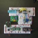
The photo shows my paper stencil ready to use and taped down on a PCB. The next step will be to spread soldering paste over to fill in the holes. Then the extra is scraped off.


