

Introduction: Making an Autonomous Boat Using a Raspberry Pi (WiP)


The wave of enthusiasm for the Raspberry Pi has driven many people to wonder at the possibilities, and marvel at it's simplicity. The credit card sized SBC is perfect for just about anything. Maybe even for crossing the Atlantic Ocean.
FishPi is a project with the goal of doing just that and crossing the Atlantic, using the Raspberry Pi to pilot the craft. The first step in this project is the Proof-Of-Concept Vehicle (POCV).
The POCV will test the basic principles of autonomous control with a Raspberry Pi, and I'm going to show you how to make your own.
Love 3D printing? Love T-Shirts?
Then you need to check out steps-per-mm.xyz!
It is loaded with a huge range of wearable Parts & Components.
Step 1: Parts


The core components used in the FishPi Proof-Of-Concept Vehicle are;
- Model B Raspberry Pi.
- 8gb SD Card.
- Models By Design Fibre Glass Hull.
- Models By Design 40mm Kort Nozzle.
- Raspy Juice.
- Flytron Navigatron V2 i2c GPS.
- CMPS10 - Tilt Compensated Compass Module.
- Adafruit 16-Channel 12-bit PWM/Servo Driver - i²c interface - PCA9685.
- Mtronics MicroViper Marine10 Electronic Speed Controller (ESC) .
- MFA 919D 540 Motor With Attached Single Ratio Metal Gearbox 2.5:1.
- Raboesch Brass 4 Bladed Kort Propeller.
- Raboesch Waterproof Propshaft.
- Kinobo 5 Megapixel USB Webcam.
- Six 5000mAH 1.2 Volt NiMH SubC cells.
- Flytron 3.3v & 5v Tiny Regulators.
- Digital Temperature Sensor Breakout - TMP102.
Tools;
Additional Parts Used (Update One 18/3/13);
- TP-Link TL-WN722N High-Gain Wi-Fi USB Dongle.
- RockBLOCK Satellite Communicator.
- SMA Female to SMA Male Panel Mount Pigtail Extension Cable.
- 2x 45mm M3 Spacers.
Please help support my work here on Instructables and on Thingiverse
by using the following affiliate links when making purchases. Thanks :)
Step 2: The Incredible Hull


The hull I am using for the POCV is based on the Cygnus Marine DS25 Fishing Boat. It is made by a company called Models By Design, they specialise in G.R.P. model boats. The hull costs a little over £20, perfect for low budgets.
To begin with the basic components going into the hull are the Motor, Kort Nozzle, Propshaft, Propeller, and servo. The DS25 is not designed to run a Kort nozzle, but as this system works well at low RPM and high torque, I decided to trial the Kort system with a view to using it in our larger vessels.
The first step is to find the centre line of the hull. To do this is I simply held a ruler against one side of the keel and carefully drew a line along the underside of the model. Repeating this on the opposite edge put two lines on the underside. Next it was just a case of measuring the distance between the two lines and marking up the centre.
To locate holes for the Kort nozzle I had to approximate where the nozzle would be best situated, I did this by viewing the hull side on and taking measurements to get the correct distances.
Inside the hull is a wooden support. This support forms the upper brace for the Kort nozzle, and provides the lower brace for the rudder servo. The support is held in with epoxy resin.
Once the Kort was fitted I used a similar method to locate a hole for the propshaft. The hole for the propshaft was slightly elongated to allow for minor adjustment in height. As long as the elongation was in the vertical plane there should be no deviation off centre in the horizontal. Before finally cementing the propshaft with epoxy take note to align the propshaft with enough room to give the propeller clearance inside the Kort nozzle, even when the nozzle is being steered.
I found that by following the mantra of measure three times, cut once, I reached an accuracy of about 0.5 of a mm when positioning the propeller.
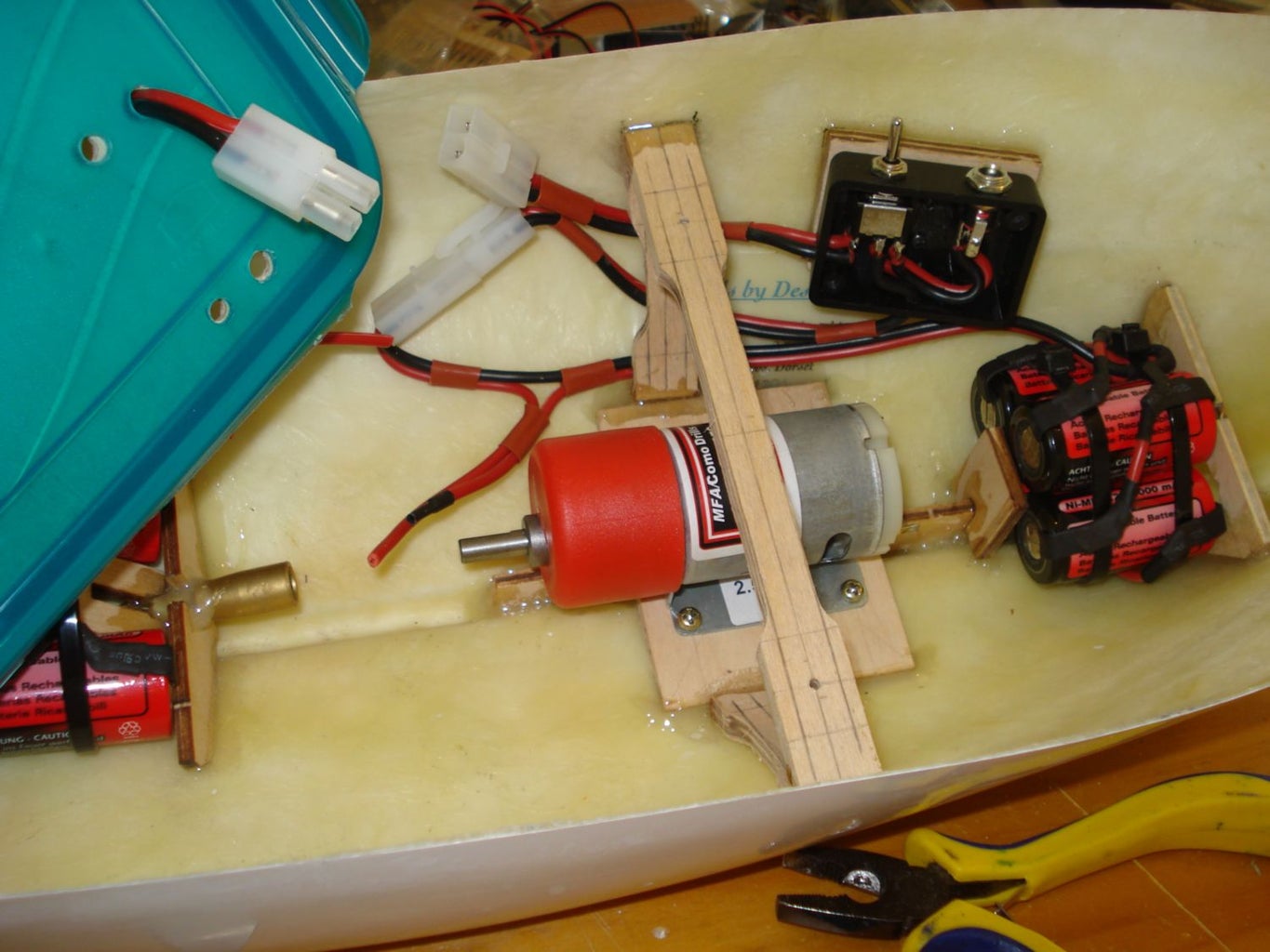
Step 3: Shafted


The MFA 919D 540 Motor is fitted with a single ratio gearbox. It increases the motor's torque, but lowers the RPM. It should have no problems driving the 40mm Kort propeller.
The motor needs a strong base to mount onto inside the hull. The underside of the mount is angled to match the slope of the hull. A centre pane slots into the keel giving additional strength.
At the rear the upper servo bracket is added. A universal joint connects the motor output to the propshaft. Some time must be spent correctly aligning the two before permanently fixing the propshaft and motor mount in place.
Step 4: Elastictrickery


Electricity & electronics do not fair well in water. I thought sometime about how to enclose the electronics in a watertight compartment. I looked at several options and in the end I settled on a plastic food storage box.
Why? Well it was cheap, about £3, there are no screws to secure the lid, and they are watertight. The particular box I chose had enough space for the Raspberry Pi, and the four clips which secured the lid to the base were on the lid itself. By building the electronics onto the lid and effectively turning the tub upside down I could un-clip the tub proper so that when it is removed all the electronics are easily accessible.
I cut & shaped a plywood board which would rest inside the lid.The whole assembly is screwed to two cross-members fixed inside the POCV's hull. The two side clips were removed from the lid so the assembly can sit lower in the hull. Onto the wood panel I glued a shaped foam pad, from a Yoga mat, which the Raspberry Pi sits on, and fitted three brackets to hold the Raspberry Pi in position. With the tub, now the lid, clipped in place the enclosure is completely watertight. For now anyway!
Step 5: Wired


Originally the plan was to connect the POCV to a Base-Station via a wired link called we termed as the umbilical. The link would provide connectivity for USB, HDMI, & CAT5e. In total there were 32 separate wires across the USB, HDMI, and Network cables. The design utilised a 32 pin aviation style connector and a 2 metre cable.
Wires would connect to the Raspberry Pi, pass through the lid of the watertight compartment and into the 32-pin connector. This would then be replicated at the other end where the cable would plug into an LCD, USB hub, and a offer a network connection.
Recently this system has been removed as it caused too many problems. The umbilical is being replaced with a Wifi link. Details of this conversion are shown later on.
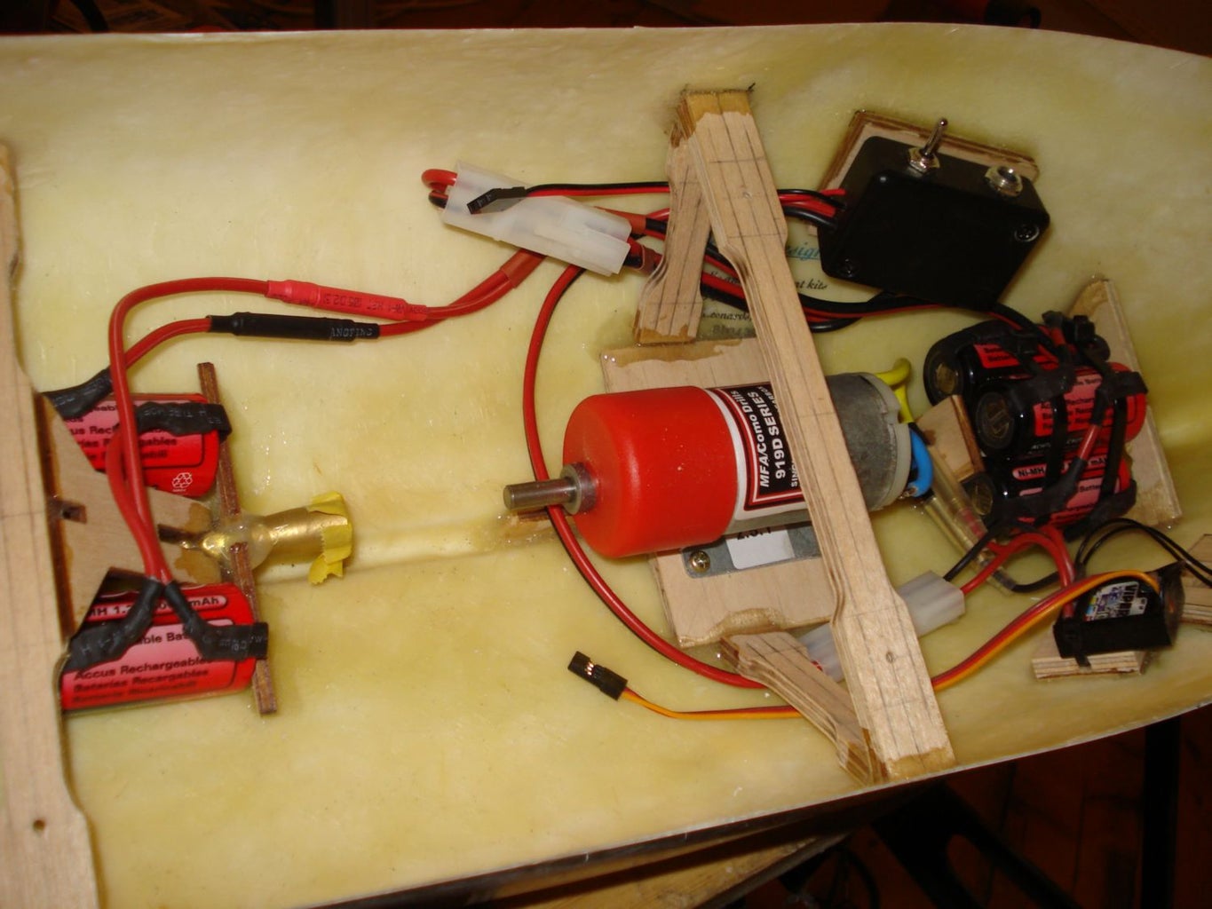
Step 6: Staying Power


Six 1.2v 5000mAh SubC NiMh batteries. Quite a mouthful, they all need securely fitting into the POCV's hull, along with a switch control box.
The box switches the battery connections between a DC socket, and supplying power to the POCV. By plugging a NiMh charger into the DC socket, and with the switch it in the correct position we can charge the six cells without needing to remove them from inside the hull.
To help balance the board I put two at the rear, below the tub, and four at the front. They are held in with tie-wraps. I have used several connectors so that the batteries can be removed if necessary.
Step 7: Power Rails


The six NiMh cells are arranged in series, this gives 7.2 volts. The Raspberry Pi works off 5 volts, and the i2c rail needs 3.3 volts.
I bought two 5v, and a single 3.3v LDO regulator from Flytron. The extra 5v would be used for any other devices, like a webcam and the Adafruit PWM, that would be built into the POCV.
The LDOs convert any difference in voltage (7.2v to 5v, 3.3v) into heat. I used a passive heat-sink removed from an old mainboard, cut it into lengths that loosely matched the shape of the LDOs, and then strapped the LDOs to the heat-sink with a bit of thermal pad between the LDO and the heat-sink. This design was later updated where the tie-wraps and thermal pads were replaced with thermal adhesive. The three LDOs are screwed to tabs glued onto the wood panel.
The i2c rails are made from strip-board. Lines for +v, gnd, SDA, & SLC, are connected with 2.54mm pins. 3.3v is fed from the 3.3v LDO. Included on the i2c rails are two 1k8 pick-up resistors.
Mounted to wooden blocks at the front is the Mtronics MicroViper Marine10 ESC.
Step 8: The Little Things


The TMP102 Temperature Sensor, Navigatron v2 GPS, CMPS10 Compass, and the Adafruit 16 Channel PWM all connect to the i2c rails using 2.54mm pins. By encasing DuPont connectors in wood, and then gluing them to the wood panel I was able to fit all the devices into the tub, and make them all removable.
CMPS10 Compass needs to be as far away from other electronics as it is susceptible to interference. The compass is mounted inside a plastic box on a mast at the front of the POCV.
To check that all the power systems work the POCV is plugged into an LCD and turned on.
Step 9: I Spy


The small form factor of the Kinobo Webcam combined with its practical rectangular shape are the main reasons for picking this camera.
One of our goals is to be able to record and hopefully transmit live images back from the mid Atlantic. I decided early on that adding in a webcam would be a addition to the POCV. The Raspberry Pi Foundation are developing a camera to work with the Raspberry Pi, but at the time of writing this the camera is not currently available.
Step 10: Spray 'N Pray


Take care when masking the hull making sure to to cover the holes, plastic parts, and any other areas where you do not want paint. I used a bin liner and modelling masking tape.
The model is hung outside on a modified wire coat hanger for spraying.
The lettering is Letraset Transfers. The letters are applied after painting, and several coats of protective varnish are sprayed over the top. The interior of the hull also gets a few coasts of the protective varnish.
The hooks around the edge are one part of a Hook & Eye system designed to hold a cloth cover over the top of the POCV.
Step 11: Putting It Together


Putting the POCV together for the final assembly I had to pass the wires through the wood panel and solder the 32 separate wires to the 32-pin connector. The first attempt didn't work very well and I had to rebuild the entire cable, at both ends, using heatshrink over all the pins where the wire soldered on. In the end it proved to complicated too make it a practical solution.
Step 12: The First Modification


As with all prototypes, things need altering from their original design. The first modification to the POCV was the Raspy Juice. The LDO supplying the Raspberry Pi with 5v was getting very hot, even with the heat-sink. Luckily FishPi had been sent two Raspy Juice beta boards for testing so it was a simple case of unplugging the LDO and wiring in the Raspy Juice.
The next upgrade was the USB hub. Removing the umbilical and installing a Wifi link between the POCV and the Base-Station. The power needs of the Wifi Dongle would exceed the capabilities of the Raspberry Pi's on-board USB. So a powered USB hub was needed. I had an old 4-Port un-powered USB hub which I modified to take a 5v feed from the unused LDO which used to power Raspberry Pi.
There are still a few additions to go onto the POCV, including a Satellite Communications Module (RockBLOCK), I will post updates as the Proof-Of-Concept Vehicle's development grows.
Step 13: Software


FishPi is no different. The Command & Control software under development for the POCV is open source. We have a repository on GitHub (link) where you can download a copy of your own, or help with development and fork from our repository. You can follow software development updates on twitter @TheFishPi_Dev.
For now we have manual control of the POCV through the Command & Control software. Al Gray, our lead programmer, is working hard to adjust the system to handle the new remote requirements imposed by the substitution of the umbilical for a Wifi link.
Ultimately we should have a system capable of autonomous navigation, satellite communications, live video feeds, and remote control. The Command & Control program should also work on any vehicle type, not just boats.
For more information about FishPi please visit our website http://www.fishpi.org, join our forum http://fishpi.org/forum/, or follow us on twitter @TheFishPi. We also have a wiki if you're looking for the full technical details http://wiki.fishpi.org/
Step 14: 18 March 2013 | Update One


After checking the eLinux.Org list of Raspberry Pi Verified Peripherals for a compatible Wi-Fi dongle I chose the TP-Link TL-WN722N. The TP-Link has a detachable High-Gain Antenna which will be perfect to use with an RF extension.
The first job is to remove all the unwanted plastic casing from the dongle. Because I will be soldering a wire to the dongle I have also unsoldered the USB plug.
There isn't much space left inside the lunch-box enclosure so the RockBLOCK will be mounted on PCB supports where it will sit above the Raspberry Pi. I used eight 12mm M3 brass supports during the modification, but I have since replaced them with two 45mm M3 supports.
The Wi-Fi Dongle sits vertically inside two notched wooden support posts, one is permanently fixed but the other is held in by a screw. Both the Wi-Fi Dongle and the RockBLOCK have USB cables soldered directly to the PCBs.
The lunch-box base, now the cover, has been drilled and an RF extension cable mounted inside the hole. The antenna which somes with the Wi-Fi Dongle has been screwed to the extension. The other end of the RF extension attaches to the Wi-Fi Dongle.
Additional Parts Used;
- TP-Link TL-WN722N High-Gain Wi-Fi USB Dongle.
- RockBLOCK Satellite Communicator.
- SMA Female to SMA Male Panel Mount Pigtail Extension Cable.
- 2x 45mm M3 Spacers.
The Base-Station is now an instructable too | Creating A Base-Station For Use With An Autonomous Vehicle.

Participated in the
UP! Contest


