

Introduction: Math Blox

Math Blox is a tangible fun math quizzes game.
Watch the video above to see how it works! https://www.youtube.com/watch?v=90Q0cenjk-c
The game is designed for the Blox Board (described here) that shows the player a set of four numbers along with a target number and it is the player's objective to use arithmetic to get the target number.
Math Blox's goal is to make learning math exciting and it is inspired from the 24 Game in which players are given four numbers on a card from 1-10 and must use arithmetic to reach the number 24. Unlike the 24 Game, Math Blox does not have duplicate numbers, each operator can be used only once and the target is an integer between 1 and 54.
The Blox Board is a generic game board programmable via an Arduino Mega that allows up to 15 unique readable pieces on 11 squares. A Blox is a binary-circuited game piece where the wiring inside of it is readable based on the number and positioning of completed circuits. For example, the software and the block labels can be modified to implement a variation of the game Mastermind or other games with similar nature.
This instructable was made by Anis Abboud and Brendan Fruin as part of the CS graduate course "Tangible Interactive Computing" at the University of Maryland, College Park taught by Professor Jon Froehlich. Please see http://cmsc838f-s14.wikispaces.com/MathBlox for more details.
Step 1: Parts and Hardware
- TinkerCad Design
- Arduino MEGA 2560: http://www.amazon.com/Arduino-MEGA-2560-R3/dp/B006H0DWZW
- Graphic LCD 84x48 - Nokia 5110
- Concave Button: SparkFun
- External Battery Pack with USB Output
- Buzzer (speaker)
- 55x Neodymium Magnets: Home Depot
- 60x Ceramic Magnets: Amazon
- 12x 3D Printed Pieces: TinkerCad Design
- 11x 3D Printed Border: TinkerCad Design
- 55x 1 1/4'' Zinc Nails (conductive)
- Piece of Indoor Wood
- Cardboard
- Wire
- Foam
- Optional: Packaging Styrofoam (to secure nails and board)
- Optional: Pipe Cleaners (to group wires)
Step 2: Designing the Border


Refer to the images for directions using TinkerCad to generate your border pieces or download them from:
Step 3: Designing the Blox


Refer to the images for directions using TinkerCad to generate your Blox pieces or download them from:
Step 4: Creating the Board


Take the eleven printed board pieces (described in Step 2) and line them up on the wood board so that each piece is touching the piece(s) next to it. Gather five nails and five 3/8" neodymium ring magnets and hammer the nail through the center hole of the neodymium magnets in each of the five holes of the border securing the border to the wood. Repeat this until all of the border pieces have been secured to the wood. It is easier if each of the holes is pre-drilled with a drill bit smaller than the nail.
Carefully flip the board over so that the point of the nails can be seen going through the bottom of the board. Notice that the nails are clustered in groups of five corresponding to the borders on the top of the board. The four corner nails of each cluster correspond to reading from the block while the center nail gives ground (0 V). The Arduino input pins are set to INPUT_PULLUP mode (HIGH by default), so when a block is positioned on the board, some of them will be grounded (LOW) and this is how we identify what block is put on the board.
If available, get four different colors of wire and cut the wire long enough so that each of the corner nails can reach the Arduino with the wire. Solder the wires with the same color in the same position to make it easier to later connect to the Arduino. Group each of the four corner wires together using the pipe cleaners or tape. Measure one wire to extend from the farthest left center nail to the farthest right center nail and solder this wire to both ends and all middle nails in between. Measure and solder one more wire from the center nail in the middle of the board to the Arduino.
Step 5: Creating the Blox


The Blox will be in two pieces after the 3D print (described in Step 2). The bottom, larger port has five large holes with 5 small holes extending from the center of the larger holes through the piece. The top piece is smaller and has an 'x' shape.
The bottom part of the Blox piece will contain five ceramic magnets some of which will have a wire extending through the smaller hole. Since the ceramic magnets are not conductive, they will be wrapped in copper tape. To avoid loose connections, we placed packaging foam in between the bottom of the magnet and the copper tape to force a connection. Note that when the bottom of the magnet is referred to it is the opposite of the top of the neodymium magnets hammered to the board. This ensures that the Blox will be attracted to the board and will enable a circuit to be created.
Wrap 60 magnets with copper tape with foam in between the bottom of the magnet and the copper tape. Cut 38 5cm wires and solder them to the top of 38 of the magnets. Put one of the magnets soldered with wires into each of the center Blox holes and put the remaining magnets with wire in the same way as the binary pattern image above. Fill the remaining holes with the magnets with no wire. For each wire of the corner wires, bend them so that they touch the center wire and solder them together. Clip any extra wire so that the top piece can cover the bottom piece. Apply super glue to each of the bottom pieces and press its corresponding top piece for 20 seconds to attach the two pieces creating a Blox.
Step 6: Arduino and Accessories
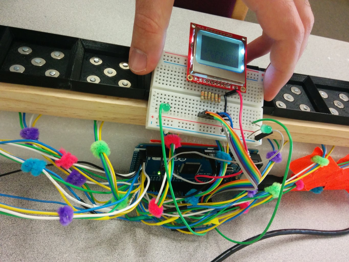
We are now ready to connect the board to the Arduino Mega. Connect the wires to the following digital I/O ports with the top left being the lowest port and the bottom right being the highest port.
Border 1 - digital pins 0-3
Border 2 - digital pins 14-17
Border 3 - digital pins 18-21
Border 4 - digital pins 22-25
Border 5 - digital pins 26-29
Border 6 - digital pins 30-33
Border 7 - digital pins 34-37
Border 8 - digital pins 38-41
Border 9 - digital pins 42-45
Border 10 - digital pins 46-49
Border 11 - digital pins 50-53
Notice that we left the digital pins 4-13 empty since we will use some of these for our LCD display. Follow this SparkFun guide to connect the LCD to the Arduino. To connect the LCD connect the following using the appropriate resistors mentioned in the SparkFun guide:
VCC - 3.3V
GND - GND
SCE - digital pin 7
RST - digital pin 6
D/C - digital pin 5
DN - digital pin 11
SCLK - digital pin 13
LED - digital pin 9
Place the board on the foam so that the nails secure the board into the foam. Dig a hole through the foam just big enough to fit the concave button. Connect the button to the Arduino's digital pin 4 and connect the buzzer to digital pin 12.
Download the Arduino software being sure that it supports the Mega (might need version 1.5.6 Beta). Download the Math Blox code from GitHub and open the ino file in the Arduino software. Compile and run this code on the Arduino Mega and you will have your own version of Math Blox which can be run independently on an external power supply!


