

Introduction: Mechanical Bicycle Seismograph


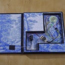
The bicycle seismograph is a mechanical drawing machine, which records the bumpiness of a bike ride on a small, rotating paper roll. The idea was born from my shaky experiences of riding the uneven roads of Berlin with my old bike.
In summer 2016 I gave a "Data bicycles workshop" at the A/D/A festival in Hamburg, where we built the seismographs. You can find more documentation here!
Step 1: Materials & Tools


Attached are detailed lists of parts and materials needed for the bicycle seismograph. There are two parts lists, one for a large and one for a smaller seismograph. These are identical except that the small one is reduced in height and works thus for paper rolls that are vertically shorter. Below is an overview of the materials and tools needed for building a seismograph.
MATERIALS
The materials for the bicycle seismograph are mostly from hardware store:
- 10 mm lightweight plywood (I used material, which is called Pappelsperrholz in German)
- 4 mm steel rod
- 5 mm steel rod
- aluminum pipe with 10 mm outer diameter
- aluminum pipe with 6 mm outer diameter
- plastic pipe or similar which slides smoothly over 5 mm steel rod
- 2 mm welding rod
- Wood screws (TX 20, 4.0 x 35 mm)
- Strong double-sided tape
- Strong fabric tape or similar
- Masking tape
- Screw terminal where 4 mm rod fits inside (e.g. 16mm2)
- Small tie-wraps (3.6 x 140 mm or a bit smaller)
- Large tie-wraps (7.8 x 200 mm or longer)
- M4 washers (hole 4 mm)
M10 washers (hole 10 mm)
Other materials needed:
- Mechanical speedometer (please see the photo) - Note that this kind of meter works best with basic bikes, but it might not work/might need adjustment with more hi-tech front wheel hubs!
- Ballpoint pens (only inner part is needed, must be plastic)
- Textile rubber band (I used 1.5 mm thick one)
- Cash register rolls. I used for the large seismograph thermal paper rolls with height of 112 mm and diameter of 44 mm (25 m of paper), and for the small seismograph regular paper rolls with a height of 76 mm and diameter of 63.5 mm (40 m of paper). Both types of rolls had a 12 mm hole in the middle.
- Fischertechnik spur gear, 40 teeth or similar (please see the photo)
- Fischertechnik worm gear or similar, which fits the spur gear (please see the photo)
- Fischertechik "axis blockers" or similar, I used 1 cm long ones (please see the photo)
TOOLS
- Electric saw for sawing wood plus adequate safety gear
- Small piece of sandpaper for sanding the wood edges
- Metal saw for sawing the rods and pipes
- Flat and round files for filing the ends of rods and pipes
- Vise for holding the rods and pipes when sawing
- Clamps for holding wood pieces
- Table drill and/or a cordless drill plus adequate safety gear
- Drill-bits of sizes 3 mm, 3.5 mm, 4 mm, 4.5 mm, 5 mm and 10 mm
- Drill-bits for TX 20 Torx screws
- Small flat tip screw driver
- Rulers and a straight angle
- Scissors, cutting knife and a cutting surface
- Pencils and a thin permanent marker
- Cutters for cutting welding rod and tie-wraps
- Pliers for bending welding rod
- Lighter
- Spanners for opening/tightening bicycle screws

Step 2: Measure and Cut Wood Pieces, Rods and Pipes


Measure and cut wood pieces (#1-#6) and rods and pipes (#7-#14 ). Please refer to the parts list attached earlier regarding the materials and sizes.Note that there are two differently sized seismographs, a larger and a smaller one. There are parts lists for both sizes. Measure the parts accurately and mark part number on each part. Use vise for holding the rods and pipes in place while sawing.
Sand the edges of wood pieces and file also the ends of the metal rods and pipes so that they are smooth. The pipes and rods will fit much easier to holes later if their ends are slightly rounded with a file.
Note also that the inside of the 6 mm aluminum pipe needs to be first drilled bigger with a 4 mm drill-bit before cutting the pipe (parts #11)! Be aware that the pipe gets hot when drilled. The idea is to fit the aluminum pipe pieces over the 4 mm steel rod (worm gear axis) so that they are not too loose.
Pay also attention to the following:
- Do not mix the rod/pipe sizes (e.g. 4 mm and 5 mm steel rod)
- Use the existing, straight edges of the wood and the 90 degree tool for straight lines
- Sawing rips off wood easily, so do not saw too fast
- Remember that sawing takes off material from wood, rods and pipes!
- Use masking tape and a permanent marker for marking where to cut rods and pipes
- Do not place the sawing mark too far from the vice, as the pipe/rod may bend while sawing
- Be careful not to press the pipes too much with the vice or they will deform
- Knife can be used instead of a file for smoothing the plastic pipe edges
Step 3: Drill Holes to the Wooden Parts


The following wooden parts will need drilled holes: #2, #3, #4, #5s, #6
Print the attached hole templates, which indicate hole sizes and positions for the wood pieces. Be sure to print the templates without scaling in 100% size.
Cut the templates first accurately with a cutting knife. Next, tape them on the wood pieces with double-sided tape. It makes sense to drill on one go the parts that have identical holes (parts #5) or nearly identical holes (#2 and #3). Tape these pieces together and drill them on one go, but be careful not to use too much double-sided tape or it is hard to get the pieces off each other. Leave the paper templates on the wooden pieces until they are drilled to the back plate later, as this way you can tell the piece orientation easier.
Note that part #1 (seismograph back plate) will also need holes for attaching it to the bike with tie-wraps, but these should be made in the very end, when fitting the seismograph to the bike.
Pay attention also to the following:
- Place an extra piece of wood under the wood pieces when drilling (prevents ripping of the wood)
- Parts #2 and #3 can be drilled on one go, but note that there is one more 10 mm hole in #2
- Pre-drill a smaller pilot hole for the 10 mm holes if you want to be very accurate
- Make sure that the holes for the gear axes are large enough for the axes to rotate (can be filed a bit larger)
Step 4: Draw Part Positions on the Back Plate

Using the attached seismograph layout diagrams, which indicate the distances of the wooden parts, draw the positions of parts #2, #3, #5 and #6 on the seismograph back plate (#1). Note that the diagrams are not in real size (printable on A4) and there are two different diagrams, one for the small seismograph and one for the large one. Start by drawing the top and bottom margins (2 cm) and draw next the positions of parts #5 and #6. You can now draw also the positions for parts #2 and #3 using the already drawn lines as a guide.
Step 5: Attach Parts #2 and #3 With Tape

Remove the drilling template from parts #2 and #3 and attach them to the back plate with double-sided tape so that no extra tape is visible, as the pieces will be drilled at a later step. Be careful to tape the pieces the correct way around and part #2 on top.
Step 6: Attach Stoppers for Roll Holders


There are two “sticks” for holding the paper rolls, #12 for the left side (10 mm aluminum pipe piece) and #8 for the right side (4mm steel rod piece). Each of them will be placed through holes in wooden parts #2 and #3 and should have a stopper so that they do not slide through the holes. For part #12, attach few rounds of ca. 2 cm wide fabric tape in the end of the pipe as a stopper. For part #8, use one of the Fischertechnik axis blocker parts (#19) or something similar that is about 1 cm high.
Step 7: Connect Rods and Pipes to Parts #2 and #3

Push the rods and pipes (#7s, #8, #10s, #12) to correct positions through the holes in parts #2 and #3. When placing the 5mm steel rods (#10) on their place, slide one of the two plastic pipe pieces (#14) on each rod - they will be attached to the pen holder later. If the rods and pipes do not go through, file the holes slightly bigger, but be careful not to make them loose, as the sticks and pipes should remain tightly in their places.
It is also a good idea to try to fit the full paper roll in its place at this point with the leftmost aluminum holder stick (#12) in order to see that it fits nicely. The roll can be then removed and added to its final place later.
Step 8: Drill Parts #2 and #3 in Place

Measure first the positions for the TX 20 / 4 x 35 mm wood screws (#26) on the reverse side of the seismograph back plate. Three screws would be good with two screws ca. 2 cm from the left and right edges and one in the middle of #2 and #3. Be careful to place the drill marks in the middle of the 10 mm thick wood boards (#2 and #3), as otherwise the wood might crack when drilling. Once the marks are in place, pre-drill a 3 mm hole for each screw and attach the actual screws after this using a cordless drill.
Step 9: Assemble the Pen Holder

The wooden pen holder part #4 should have one 10 mm hole already drilled in the middle and six 3.5 mm holes on the sides. Push the pen holder pipe #13 through the 10 mm hole so that it is in the middle. Place after this three M10 washers (#28) on one side of the pipe, against the wood. Then, attach a piece of fabric tape as a stopper in the end of the pipe so that the washers do not slide out. Do the same thing on the other side of the pipe so that you have 3 washers symmetrically attached on each side of the pen holder.
Note that the washers act as weight and influence how the pen moves up and down when riding the bike. You can later adjust the amount of the weights if you need more or less sensitivity.
Step 10: Attach the Pen Holder

The pen holder is to be attached between the plastic pipe pieces (#14) that slide over the 5 mm steel rods (#10). Place first some fabric tape over each plastic pipe, so that there is some friction for the tie-wraps, which are attached next. However, the plastic pipes should still slide freely on the steel rod rails, so avoid putting too much tape. My plastic pipe was 7.5 x 1 mm and I put ca. 2.0 x 3.0 cm piece of the fabric tape over each pipe piece, so that the part of the pipe, which was touching the wooden pen holder was not covered by the tape.
When you have found a good amount of tape, attach the pen holder with ca. 3.6 x 140 mm tie-wraps (#24) through the four outermost holes on the pen holder. Test again that the pen holder slides effortlessly up and down on the rails and cut the remaining tie-wrap pieces short if all is ok. If the holder does not slide well, try to adjust the construction in order to have a well-sliding holder.
Step 11: Attach the Big Gear to the Roll Holder


Assemble first the Fischertechnik spur gear (#17) by placing the red hub part (#20) in the middle of the gear. The gear is to be attached to the lower part of the rightmost paper roll holder (4 mm steel rod, #8), over which the paper is winding when pedaling. You need to have about 2 cm distance for the spur gear from the wooden part #3, so that the spur gear will be aligned with the worm gear (#18). I used for this two 1 cm Fischertechnik "axis blocker" pieces (#19), after which I attached the spur gear. Whatever you use, make sure that the spur gear axis can still rotate smoothly.
Step 12: Attach the Worm Gear Axis Holder Parts #5

The positions for the two wooden #5 pieces should be already drawn on the seismograph back plate. The pieces should have still the drilling templates on them, so look from the templates which way the pieces should be placed - correct orientation is very important! Next, remove the templates and tape the #5 pieces to their positions using double-sided tape so that no extra tape is visible. Again important:test that the wooden pieces fit nicely around the spur gear, so that the gear rotates still smoothly.
The wooden pieces #5 serve as an axis holder for the worm gear (#18), which will be connected to the spur gear, resulting in speed reduction that allows the paper roll to spin slowly. This construction will be assembled in more detail in the next step, but at this point, test that the positioning of the holder pieces is correct. Place the axis (#9 steel rod) through the holes in the holder with the worm gear over it. Check that the axis rotates smoothly and that you can place the worm gear over the spur gear so that the teeth of both gears align nicely. It may be that there are small inaccuracies due to sawing and drilling of the pieces and that the match is not perfect, so you might need to adjust the axis/worm gear position. For example, if the axis is too low, you can add another piece of double-sided tape under the axis holder pieces.
If everything seems fine, attach the wooden holder pieces on their place from the reverse side of the seismograph back plate using two wood screws (#26). As before, mark first the screw positions, then pre-drill 3 mm holes and finally attach the screws with a cordless drill.
Step 13: Attach the Worm Gear to Axis - Requires Precision!


Place the worm gear axis (4 mm steel rod, #9) at its place, pushed through the holes of the wooden axis holder pieces (#5). Next, place a small Fischertechnik blocker (#19) or something similar on the outside end of the axis so that ca. 1.7 cm of the axis remains outside the rightmost wooden holder piece.
Next, the worm gear (#18) will be attached to its axis, so that it will rotate as the axis rotates. For attaching the worm gear, the two aluminum pipe pieces #11 are needed (6 mm pipe, which was earlier drilled bigger). Before attaching the parts, a small dent has to be filed to the aluminum pieces so that they fit to the shape of the worm gear ends.
Once the aluminum pipe pieces fit nicely with the worm gear ends, they will be placed on the axis on both sides of the worm gear so that there are also small M4 washers (#27) on the outer edges, against the wooden axis holder pieces. The rightmost aluminum pipe should be placed close to the washer, while there should remain a gap between the aluminum pipe and the washer on the left side.The worm gear should also be over the spur gear so that the worm gear rotates the spur gear. This gear mechanism reduces the speed at which the paper roll rotates when bicycling.
In order to attach the worm gear (#18) to its axis, attach first a small piece of tape around the axis in the gap between the left washer and the aluminum pipe. Wind the tape around the axis until the tape and the aluminum pipe have the same diameter. Make sure that the axis can still rotate freely. Next, add a second piece of tape over both the first tape and the aluminum pipe. This way the aluminum pipe pieces and the worm gear are locked in their positions and move as the axis rotates, and the worm gear rotates the big gear as desired.
Step 14: Attach Support Piece #6 and the Speedometer Cable


Place piece #6 in the correct position. Look what is the correct orientation of the piece from the drilling template, which should be still attached to the piece. Once you have it, remove the template and tape the piece in its place using double-sided tape so that no extra tape is visible.
Before drilling the wooden holder piece in place, do some fitting in order to see that the position is good. Place one end of the speedometer cable on the support piece in order to see whether the “stick” inside the cable is aligned with the worm gear axis.Be sure to use the correct end of the speedometer cable, so not the one that should be attached to the plastic piece on the front wheel. The stick coming from the cable and the worm gear axis should be aligned, as the idea is to connect at a later step the two together via a screw terminal (#21). In case the speedometer cable would be too low, you can always add some sturdy tape around it in order to make it a bit higher. Check also that you can fit the screw terminal nicely in its place, but don’t attach it yet.
Once you have checked everything and all seems ok, you can screw the wooden speedometer cable holder in its place from the reverse side of the back plate. Use two of the same wood screws as before, mark screw positions, pre-drill 3 mm holes for the screws and finally attach the screws with a cordless drill.
Lastly, attach with a screwdriver the screw terminal so that it connects the “stick” inside the speedometer to the worm gear axis. Next, attach the speedometer cable in its place on the support piece #6 using small, ca. 3.6 x 140 mm tie-wraps pushed through the holes in the support piece.
Step 15: Prepare and Attach the Top Rubber Band Holder


Bend with strong pliers the large rubber band holder on top of the seismograph from 2 mm welding rod (#15). Please see the photo for the shape.
Attach the top rubber band holder to the 5 mm steel rods that carry the pen holder using tape and ca. 3.6 x 140 mm tie-wraps. Attach also a rubber band (#22, ca. 1.5 mm in diameter) to the dent on the top of the rubber band holder with the other end attached around the pipe in the pen holder. When attaching the rubber band, hold the seismograph upright, as it would be on a bicycle, so you can see how low the pen holder hangs. The tension of the rubber band should be such that the pen holder is near the middle (not too low or high, as the pen will move up and down when bicycling). It is good not to make too many knots at this point and to leave a bit extra in the rubber band, as it can be that the rubber band needs to still be adjusted depending on how well the pen holder moves.
Step 16: Bend and Attach the Small Rubber Band Holder and Pen


Bend the smaller rubber band holder, which is attached to the pen from 2 mm welding rod (#15). Please see the photo for the shape.
Take the inside tube of a regular ballpoint pen (should be plastic). Use a lighter to gently heat the tube so that you can bend it into a curved shape, as the idea is that the end of the tube faces upwards when bicycling (otherwise the ink would stop running after a while). While bending the pen, try fitting it inside the pipe in the pen holder so you can make the angle right.
Wrap some fabric tape around pen near its drawing tip so that you attach the small rubber band holder made out of welding rod to it. There should be so much tape that the pen fits still inside the pen holder pipe, but at the same time it should be attached tight enough not to fall out (but not too rigidly). The tip of the pen should reach the back plate, where the paper will ultimately be. After checking the dimensions, remove the pen for now.
Step 17: Attach the Paper Roll

Take the leftmost paper roll holder pipe out (#12, 10 mm aluminum pipe) and place the full paper roll on the seismograph, so that the pipe goes through the spool, holding it in its place. Next, open the roll carefully and pull the paper under the 4 mm steel rods (#7) near the back plate. The idea is that these rods hold the paper down. Then, attach the end of the paper with masking tape or similar to the rightmost paper holder, which is connected to the spur gear (#8, 4 mm steel rod). The idea is that the paper is wound around this rod when bicycling.
When attaching the paper, it is best to hold the seismograph upright as it would be on a bicycle, so that the paper roll rest in its correct position. If the end of the paper roll is unevenly ripped etc., cut the edge straight before taping it. When the paper roll is well in place, you can loosen the big gear and rotate the rightmost paper holder few rounds in order to wind up little bit paper around the rod in order to ensure that it is rolling nicely.
Step 18: Attach the Pen and the Tensioning Rubber Band

Place the prepared ballpoint pen together with the small rubber band holder inside the pipe on the pen holder. Cut a piece of rubber band (#22, ca. 1.5 mm diameter) and attach it to the small, remaining holes on the wooden pen holder piece so that it goes over the rubber band holder and pushes the pen against the paper. You may need to adjust this rubber band also in case it turns out to be too loose or tight. If the contact of the pen to the paper is too loose, the pen might not draw continuously and if it is too tight, it might rip the paper.
Step 19: Attach the Speedometer Gear Part to the Bicycle

The small, grey, round plastic part of the speedometer, which will be ultimately connected to the speedometer cable, will be attached to the front wheel of the bicycle. In the case of my speedometer, the part should be placed on the left side between the fork and the wheel, so that the small silver-stick is in between the spokes and can rotate freely 360 degrees. The movement of the wheel is then conveyed via the speedometer cable to the seismograph, where it rotates the paper roll, slowed down by the reduction gear mechanism. Once the grey plastic part is attached, check that the seismograph gears move correctly and in the correct direction when the front wheel spins.
Important:
When the speedometer cable is not attached to the grey plastic part attached to the front wheel, the opening of the grey part should be tightly taped, as otherwise tiny parts of the speedometer’s gear mechanism can fall out and it will not work anymore!
Be sure to also tighten the screws of your bicycle wheel tightly and test carefully that your bike is safely and comfortably ridable before making any longer bicycle rides!
Step 20: Attach the Seismograph to the Bicycle


Find a good spot in the front part of the bicycle where the seismograph fits so the speedometer cable is not heavily twisted or on the way. The seismograph is attached with large tie-wraps of ca. 7.8 x 200 mm (#25). See how to attach the seismograph best and sturdily from about 3 different points and drill then 10 mm holes for the tie-wraps using a cordless drill. Double-sided and gaffa tape can be used also for holding the seismograph better in place and for reducing the impact of the wood hitting the metal on the bicycle.
Make a small test drive in order to see that the bicycle is safe to ride and that the seismograph works as it should. Adjust the rubber bands etc. if needed. Have fun recording bumps! :)
The paper rolls that I used lasted relatively long (some kilometers) and when the roll was finished, the end detached by itself, but you need to see if your rolls work similarly. When my roll was full, I wound it out of the seismograph by first loosening the spur gear, so that is not connected to the worm gear anymore. Cordless drill with a slow speed may also used for winding the paper.
When you have done enough recordings, you can detach the speedometer cable from the plastic part in the front wheel and remove the seismograph from the bike. If you leave the plastic part connected to the front wheel for further recordings, be sure to tape the opening on the part or small parts will fall out and the speedometer will not work anymore!


