

Introduction: Micro Sumo


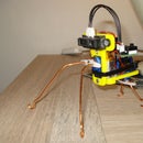
Micro Sumo is a small robot of the dimensions that can be used in a micro Sumo contest
You can also customize the Micro Sumo order to abtain something else for example special character robot, attach a pencil on the back of the Micro Sumo and you have a Draw Robot
Step 1:


As preparation I have some parts drawn with sketchup and print with my Prusa i3
Attachments


Step 2:


As a first step, I saw a square of a euro experiment board of + - 38 mm (equivalent to 14 holes)
I use two motors from a discarded 9g servo, but the motors are still good
Then place the Board in the Mal
Take a Motor and place it in the corner and at the Mal
Solder now quickly the Motor to the Board, soldering as quickly as possible in order not to cause damage to the Motor
Take the second Motor and do the same as the first but in the other corner
Now remove the Mal
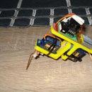
The motors are now precisely on the circuit board
Step 3:


Now comes the interesting part
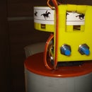
On the first picture you can see where the components are soldered honors
2x 2N2222A Transistor
2x1N4007 Diode
3x1K Resistor
2xPhototransistoren or LDR
2x10K Resistor
1xRode Led
1xATtiny85 Microcomputer
Place all the components on the circuit board
Look closely at the polarity of the components
I have the components separate the sensors from the front and drive behind
There is also a mirror image of the circuit board, this have I done that you can better see if everything is set correctly
Attachments
Step 4:


ATtiny Inputs & Outputs
Both models need only a supply voltage and no external components to function!
The remaining six pins can be used as inputs and outputs.
Advice to use only five because pin 1, which is a Reset pin but can be programmed once. The ATtiny to program thousands of times as long as you do not programmmerd the Reset pin.
This is in fact necessary for reprogramming.
ATtiny versions
They are available in 10MHz and 20MHz versions.
Full size (PDIP) and SMD (SOIC).
The input voltage varies by model 1,8Volt or 2,7Volt with a maximum of 5,5Volt.
ATtiny programming with the Arduino
The ATtiny can be programmed by using your Arduino.
Be the ATtiny with the same C ++ code work.
You have to put the Arduino into an ISP mode so that the program stopped going to work.
Supported commands are:
• pinMode ()
• Digital write ()
• digital read ()
• analog read ()
• analog write ()
• SHIFTOUT ()
• pulseIn ()
• millis ()
• micros ()
• Delay ()
• Delay microsecond ()
Present necessities in order to use the programmer
Hardware
• Arduino Uno or Arduino duemilanoveHardware
• ATtiny program held hardware
• ATtiny 45 or ATtiny 85Software
• Arduino IDE version 0023 or newer software
• ATtiny45_85 plug-in Arduino plug-in installed
Download the plugin attiny45_85
Unzip the zip file
Copy the folder to attiny45_85 arduino-0023 / hardware /
Programming the Arduino so that he will support the programmer-shield
Start the Arduino IDE 0023 software
Connect the Arduino without the programmer-shield
Go into the Arduino software to File -> Examples -> ArduinoISP
Upload program the code that appears in the image ATtiny
Place the shield with the ATtiny 45 or 85 ATtiny it.
The Arduino can just keep coupled to the USB port
If the shield is well built, the green LED should slowly and gradually go out
Click on File -> New and paste the following code in the window:
# define ledPin 4
void setup(){
pinMode(ledPin, OUTPUT);
}
void loop(){
digitalWrite(ledPin, HIGH);
delay(300);
digitalWrite(ledPin, LOW);
delay(300); }
Click Tools -> Board -> ATtiny45 (w / Arduino as ISP) OR ATtiny85 (w / Arduino as ISP)
Now upload the code
If all goes well then fire the upper green led during programming, then flashes the red LED.
You have just programmed the ATtiny.
Step 5:
This is a simple line follower program
int leftInput=3;
int rightInput=2;
int leftMotor=1;
int rightMotor=0;
int leftValue = 0;
int rightValue = 0;
void setup(){
//Serial.begin(9600);
pinMode (leftMotor, OUTPUT);
pinMode (rightMotor, OUTPUT);
}
void loop(){
leftValue = digitalRead(leftInput);
rightValue= digitalRead(rightInput);
if ( leftValue ==HIGH && rightValue ==HIGH)
{
digitalWrite (leftMotor, HIGH); digitalWrite (rightMotor, HIGH);
} else {
if ( leftValue==LOW && rightValue==HIGH)
{
digitalWrite (leftMotor, LOW); digitalWrite (rightMotor, HIGH);
} else {
if (leftValue==HIGH && rightValue==LOW)
{
digitalWrite (rightMotor, LOW);
digitalWrite (leftMotor, HIGH);
} else {
if (leftValue ==LOW && rightValue ==LOW)
{
digitalWrite (rightMotor, LOW);
digitalWrite (leftMotor, LOW);
}}
}
}}

Participated in the
Robotics Contest 2016


