

Introduction: Mini CNC Machine Arduino Based & Adafruit Driver Motor L293D V1 & 2*Mini Stepper CD/DVD Player #1


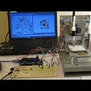

In this project I will show you how to easily build your own low-cost Arduino Mini CNC Plotter!
For X and Y axis we will use stepper motors and rails from two dvd/cd roms! Printing area will be max 4x4cm.
Step 1: The Video in Youtube :
Step 2: Parts


For this project you will need:
- Part list for beginners:
- Arduino uno ( or Mega ) Breadboard
- Shield driver motor L293D adafruit v1
- Mini Servo motor 9g
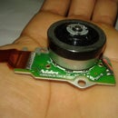
- 2x DVD/CD Drives
Librairy For Adafruit Shield Driver Motors v1 :

Step 3: X Y Axe

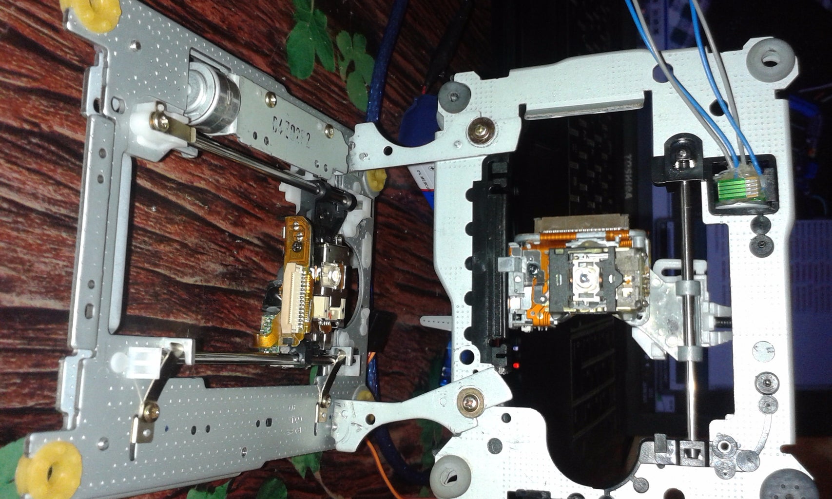


In first image above you will see the Y axis of our CNC machine. Attach it on your surface, in this part you will need some screws and nuts.
In second image you will see the X and Y axis. The X axis is attached to two plastic parts that I took from remaining 'garbage' stuff. I cut it to fit the construction. This is an easy procedure. Just make sure to put the Y axis straight to CNC base and the X axis vertically in this (90 degrees)
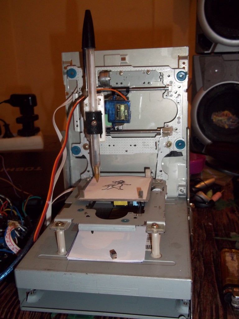
Step 4: The Z Axis


That's the most difficult part of our construction.
You will need something to attach it on X axis, a flat surface. On that surface you will attach the servo motor (Z axis) and the pen base. Pen (or pencil) must be able to move up and down with the help of servo motor. Watch the above image to understand what you need to do to duild Z axis. Tip! Use your imagination ;)
Step 5: the Circuit

Step 6: Uploading the CNC Code

Here is the main CNC code embedded using codebender!
In this part you will see your pen goes up. If don't, change penUp and penDown variables that controlling the servo motor. Press the "Run on Arduino" button and program your board from your browser!
Attachments
Step 7: Make Your Own Gcode Files
To make gcode files that are compatible with this cnc machine you have to use the Inkscape.
Inkscape is professional quality vector graphics software which runs on Windows, Mac OS X and Linux. It is used by design professionals and hobbyists worldwide, for creating a wide variety of graphics such as illustrations, icons, logos, diagrams, maps and web graphics. Inkscape uses the W3C open standard SVG (Scalable Vector Graphics) as its native format, and is free and open-source software. Download and install Inkscape from : https://inkscape.org/en/download/windows/
(Important: download 0.48.5 version)
Now you need to install an Add-on that enables the export images to gcode files. This add on can be found here with installation notes.
https://github.com/martymcguire/inkscape-unicorn
Setup Inkscape for first use
Open the Inkscape, go to File menu and click "Document Properties". See the 1st image above and make the changes, make sure to change first to "cm". Now close this window. We will use the area within 4 to 8 cm. See the 2nd image above. How to print texts Put text, change font to Times New Roman and size to 22. Now click on cursor icon and center the text like the 3rd image above. Select Path from menu and "Object to Path". How to print images This is more difficult than texts. Images must have a transparent background. Drag and drop the arduino logo image (download it from files) in Inkscape. Click ok to the next window. Now you have to re-size the image to fit our printing area, see the 4th image above. Click Path from menu and "Trace Bitmap". Make changes as the 5th image above. Click ok and close the window. Now, move the gray scale image, and delete the color one behind it. Move the grey image to the correct place again and click from Path menu "Object to path". The 6th image above show how to delete image outline. Export as gcode Final, go to file menu, click save as and select .gcode. Click ok on next window. That's it! Ready to go! Use the gctrl.pde app to print the gcode file on your new Arduino CNC Plotter! I will make a video on next days about this procedure because it's little complicated. It took me a lot of time to understand how it's working...
Step 8: The GCTRL Program

Now we are ready to print our first image! To do this we will use the gctrl . This program sends 'gcode' images to the cnc plotter.
What is gcode? Gcode is a file with X,Y and Z coordinates. Header of this file is set to: M300 S30.00 (Servo down) G1 X10.00 Y10.00 F2500.00 G1 X20.00 Y10.00 F2500.00 M300 S50.00 (Servo up)
Click the "play" icon/button to start the program.
Download gctrl for Windows :
https://www.instructables.com/files/orig/F69/K945/I...
Click First time to " p " to select Port number for Arduino
and click to " g " to select Gcode file ...


