

Introduction: Mini X-Wing Popsicle Stick Model


**** RED 5 standing by....>>>> *****
Merry Christmas everyone! Here's an instructable everyone's probably waiting for - A T-65 X-wing Starfighter from the Star Wars Saga.
Manufactured by Incom Corporation for the Rebel Alliance, the X-wing is probably the most iconic starship that ever came out from any Sci-Fi movies and/or series. Armed with four laser cannons and photon torpedoes, the X-wing holds the distinction as the ship that destroyed the Death Star (that was one very lucky shot!).
This mini popsicle stick model depicts an X-wing with the S-Foils in the attack position. This mode shows where the X-wing got its name...
The model was surprisingly easy to build (compared to the Eagle Transporter from Space 1999). The instructable is just three steps (Less the intro, tools/materials and images/schematics) with the step by step illustration consisting of only 38 images. The only real challenges were fabricating the four (4) laser cannons and carving the "bullet-shaped" fuselage. Each cannon contains four parts which I will discuss in detail later.
Step 1: Materials and Tools


Aside from the wooden dowels, popsicle sticks (various sizes too!) and toothpicks, materials used were mostly from my spares box.
Tools used for the build were as follows:
- Dremel 3000 & Dremel Minimite with the following attachments:
- Coarse and Fine Drum sander
- Fine disc Sander
- #124 & #125 High speed cutter
- Standard & reinforced cut-off wheel
- #8193 Aluminim oxide grinding stone
- Olfa cutter
- Fine tweezers
- Mechanical pencil
- Ruler
- Various multi-purpose clamps
- Elmers White Glue
- Cutting mat
Step 2: Images and Schematics


You can tell from the images available online that the X-wing is quite famous. Using "x wing" as the keyword for both Bing and Google imagesearches results in images and pictures of the X-wing in all angles imaginable. But of course the more important images are the schematics.
I used the schematics from "http://i730.photobucket.com/albums/ww307/Agent239/Star%20Wars/X-wing_schematics-1.png" as the main reference. A fuselage schematic I also relied on came from the URL" http://fc07.deviantart.net/fs71/i/2010/247/d/5/x_wing_blueprint_wip_by_imclod-d2y0gij.png".
Additional images I used in this instructable were from:
http://fc02.deviantart.net/fs70/i/2012/144/3/0/x_wing_revisited_by_hikaru84-d50sz14.jpg
http://www.swgemu.com/archive/scrapbookv51/data/20070204120429/x-wing_s01.jpg
I specially liked the image from deviantart. Not only does it provide details on the X-wing but is strikingly reminiscent of the original promotional picture from the movie back in the 80's. Again, my thanks to the providers of the images for making this build possible! Merry Christmas again guys!:)
Step 3: Fuselage and Wings


The fuelage was from five (5) regular-sized layers of popsicle sticks laminated together with elmers glue. The layered pieces were held in place with various clamps while the white glue dries. A rough sketch using the schematics was drawn on the sandwiched piece. A rough shape of the fuselage was carved using a coarse/fine drum sander and disc sander attachment on a Dremel 3000. The droid mount behind the pilot's cockpit was cut using a standard cutting wheel and finished
with a fine disc sander attachment on a Dremel MiniMite. The nose and hexagonal shape of the fuselage was finished with a #8193 aluminum oxide grinding stone attachment.
The droid was cut from a small dowel shaped at the end with a disc sander attachment. In order to prevent the dowel from splitting (a nasty characteristic of wood pieces..), I slice the tip just half-way using a standard cut-off wheel and then cutting it off completely with an Olfa knife. The droid was glued just behind the pilot's cockpit.
The four (4) wings were from a single tongue depressor-sized popsicle stick cut into shape using the schematics as guide. A notch was made at the rear end using a standard cut-off wheel attachment on a MiniMite.
The spares from the wing assemblies were used to make the engine mounts. Each mount was carved to an L-shaped piece using a standard cut-off wheel and finished with a disc sander attachment on a moto tool. These were glued on top of each wing and allowed to dry. Finally, the engine mounts where sanded at an angle to simulate the "Chepat Deflector Screen Projector".
Step 4: Laser Cannons and Engine Assemblies


A small wooden dowel, a toothpick and scrap materials from my spares box make up the materials for the four (4) laser cannons. I needed to sand the small wooden dowel further with a fine drum sander attachment to get the correct diameter for the laser cannon receiver. A slot was made at the rear end with the use of a standard cut-off wheel attachment on a Minimite. This step was repeated four (4) times for each of the laser cannon.
For the four (4) laser cannon barrels, a thinned toothpick was used. A disc sander attachment was very handy in shaping the two (2) sections of the barrel length.
And now for the trickiest part - making the curved "flashback suppressor" for the laser cannon. Shavings from a scrap tongue-depressor-sized popsicle stick was used. I noticed that the tongue depressor was a lot thinner than the standard popsicle stick, hence, a better choice. Each piece was further cut into shape with an olfa cutter. The part was so tiny that even a small gust can blow the suppressor right out of your sight.
The laser cannon tip was from a thinned toothpick. This part must be thinner than the laser cannon barrel and a disc sander attachment on a Minimite was used for this purpose.
Assembling the tiny pieces were even trickier. I made sure that the tip, suppressor, gun barrel and receiver were all properly aligned. This was made more difficult with the slow setting Elmers white glue as the bonding material. It took a while to put all the pieces together for the four (4) laser cannons of the X-wing but I was satisfied with the result.
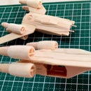
Fabricating the two (2) piece engine assembly was simplified with the use of pre-cut wooden dowels. The larger dowel was used for the main engine while the exhaust nozzle used the smaller dowel. Drilling the holes for both the main engine and the exhaust turned out to be the most dangerous part of the build. I used a #125 high speed cutter for the pilot hole and a #124 attachment to make the hole wider. The four (4) main engines and four (4) exhaust nozzles was installed during final assembly.
Step 5: Putting It All Together....


Completing the build was again a straight forward process. The schematics guided me in attaching the four (4) wing assemblies to the fuselage at the correct "attack" angle.
After the glue has set, the four (4) main engines were glued next. These were mounted on the slots left when the engine mounts were glued to the wings. Gluing the four (4) engine exhaust nozzles completes the wing-engine assembly stage of the build.
Finally, the four (4) completed laser cannon assemblies were glued to each of the X-wing's wingtips. I just made sure that the laser cannons were parallel with the fuselage and engine assemblies.
And there you have it! An X-wing ready for another trench run!


