

Introduction: Mini Y-Wing Popsicle Stick Model


***** STAY ON TARGET>>>> *****
This article shows a step-by-step guide on how to model a Koensayr Manufacturing BTL Y-Wing Starfighter straight from the Star Wars Universe!
Step 1: Materials

Materials in this project includes varying sizes of wooden popsicle sticks. Tongue depressors were specially useful for wide pieces and wood stirrers you can knock off at your local starbucks were used for smaller pieces like the Y-wing's engines.
Varying toothpicks can be used for the much smaller pieces like the Y-wing's blaster and ion cannons.
Wooden spoons were used for the round exhaust nozzles.
Step 2: Tools

Tools used in this project were basic cutting and wood carving tools. An olfa precision art knife was used but an x-acto with no. 11 blade would do nicely.
A moto tool proved invaluable for basic shaping and finishing. Particularly handy were the drum and disc sander attachments and various shapes of wood cutting bits available for dremel hand tools. Be careful in using the moto tool since you'll be shaping some really tiny parts!
White glue was the only adhesive necessary for the project. Since white glue dries soooo sllooowwwwllyyyyy, plastic clamps were necessary to hold pieces in place.
Finally, a pair of nice tweezers was used to handle and mount small parts to the much larger pieces.
Step 3: Search for Schematics

Schematics available from the internet provided the pattern to shape the major parts of the Y-wing. Keyword for google images : Y wing schematics. Download an image and scale and print a copy based on available materials at hand. The widest popsicle stick (or wooden tongue depressor) must match the widest component in the schematics. In this case, the popsicle stick must not be wider than the y-wing's main fuselage.
Step 4: Main Fuselage


For the main fuselage, the widest popsicle sticks sizes were used. I was planning to source tongue depressors from the local drugstore but luckily found a bigger (but dyed!) set of popsicle sticks from the nearest bookstore for this purpose.
I began by cutting off the rounded end with an art knife. I needed to cut 3 equal pieces to compensate for the thickness required as shown in the schematics. After gluing the pieces together and setting them to dry (at least an hour), I started shaping them with the dremel moto tool using a drum sander attachment.
I then used a smaller wooden stirrer piece, cut and shaped (like a small coffin) for the canopy. This was then glued to the main fuselage and set aside to dry.
Parts of the 'scrap' from the main fuselage was cut into a trapezoid and glued at the bottom of the fuselage to simulate the photon torpedo 'bulge' launcher. After this has dried, it was then shaped by using the moto tool with the drum sander, rounding of the edges and beveling the front. Please take note of the shape of the individual parts based on the schematics.
Step 5: Astrometrics and Hyperdrive Module


To model the astrometrics and hyperdrive module that connects the main fuselage with the main engines, regular sized popsicle sticks were used.
These were first glued together and set aside to dry. Guide lines were drawn based on the schematics and shaped using the moto tool.
A large toothpick (a barbecue stick will also do nicely) was rounded at the end using a moto tool, cut and glued at the front of the astrometrics module to simulate an R2 unit.
Step 6:


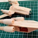
For the main engines, 'starbuck' stirrers were again used. Glue three pieces together and have them dry overnight. You'll need to get the glues really dry since a lot of carving and shaping will be needed.
Start by rounding off the square edges. You should end up with a wooden 'tube'. Cut off two pieces based on the illustrated length of the Y-wing schematics. You can then proceed to shape the front end of the rear 'nozzle'. Using a moto tool with a drum sander can take a little bit of practice to master. Don't worry if you make a mistake, materials are cheap and it's very easy to fashion a new piece based on the schematics. Once you are satisfied with the shape, set them aside for assembly at a later stage.
For the support pylons, I used similar sized toothpicks and just rounded them with a moto tool equipped with a disk sander. You'll need to cut 8 equal sizes for the two engines. Again, set them aside while you work on the 'disk vectrals' (or the exhaust nozzle).
For the disk vectrals, I used a wooden spoon I sourced from the local grocery. The rounded shape of the spoon simplifies the effort of carving the disk vectrals into a round disk. I drilled a hole on the disk, and rounded it a little until I'm satisfied with the shape. Two pieces were needed for the two main engines.
The main engine and support pylons were first to be assembled. I glued two opposite pairs per session, allowing them to dry first before mounting the next opposite pair. Again, refer to the schematics for the correct placement of the support pylons. Finally, the 'disk vectrals' were glued at the end of the support pylons. Assemble two sets for the two main engines of the Y-wing.
Step 7: Main Cannon


For the main cannons mounted in front of the fuselage, I cut a pair of really tiny pieces of pre-rounded toothpicks. Gluing them at the front is a little trickier, allowing a dab of white glue to partially dry before sticking the really tiny 'cannons' at the end with the aid of tweezers.
Once, you're satisfied that the cannons are parallel and of the right angle, dab white glue around them to reinforce the bond.
Step 8: Roof Mounted Ion Cannons and Main Engine Pylons


To model perhaps the most difficult part of the Y-Wing, I shaped the end of a toothpick using a disk sander to form a barrel. The barrel and receiver should resemble a miniature M2 browning machine gun when finished.
I carved two similar pieces of the ion cannon (aka mini .50 cal) glued them together and mounted them on top of the Y-wing canopy.
For the final parts, I cut two (2) pieces from the regular popsicle stick 'spares' to form the main engine mounts. These two parts connect the main engines to the astrometrics module (in step 5).
Step 9: Final Assembly


With all the main main pieces in place, I simply glued the major parts together to complete the Y-wing fighter-bomber.
Fabricate and assemble two more bombers to form Gold Squadron (from Episode 4)! Hope you have fun with this project!

Participated in the
ThinkGeek Sci-Fi Contest
Participated in the
Reuse Contest

Participated in the
Instructables Design Competition


