

Introduction: Mini Adjustable Power Supply


When designing this power supply, my objective was to have it as portable as possible, so you can take it almost anywhere. One of the reasons I want it to be so portable is because every time I go to visit my family and friends abroad, they always have something for me to fix (or at least “try to fix” ) They have a soldering iron, but that’s about it. That’s why I made the voltpen, this mini power supply, and a mini usb sound card oscilloscope (Instructable to follow soon).
I made other power supplies, but none of them had current regulator. This time I decided to use the LM2596 instead of the normally used LM317 or LM350, so I could also adjust the current.
The beauty of this unit is that you can connect it to any DC source from 7.5V to 28V. So I can just take it with me and connect it to a laptop power supply for example. The output voltage will be very close to the input voltage, maybe about half a volt less. It can also be use as a voltmeter without being powered for voltages from 2.5V to 30V and as an ammeter from 5V. And It’s great for charging batteries.
Enough talking, lets cut to the chase..
Step 1: Materials and Tools
I organized the materials into two categories, necessary and optional components. The prices are based on what I paid or the lowest price I could find on ebay. Normally I buy components from HK. With most of the electronic components you can buy about 10 units for the price of one in the UK. The links to ebay are the cheapest I could find.
Necessary components:
- Project enclosure Box £2.15, 72 X 50 X 41MM (Drawing) (link)
- LM2596 £1.67 (Datasheet) (It’s best to buy this little circuit (link) with all the components already there, makes it easier) Make sure you buy the version that adjusts current also, it’s easy to tell because it should have 3 trimmers on the board.
- Ammeter £2.05 (link) Please read step 5 before even trying the ammeter.
- Voltmeter £1.49 (link) Make sure you buy the one with 3 wires (black, red, white). You could use the one with only two wires, but you won’t be able to read voltages lower than 2.5V or 3V.
- BNC connector £0.20 (link)
- Heat sink for the IC £0.12 (link) Or if you want to buy the one that fits on the IC (link I thought that is just too much for the heat-sink. Maybe you could use a raspberry pi heat sink)
- Aluminium plate (reuse any aluminium you can find anywhere)
- x2 10k potentiometers £0.17 (link) (I recommend getting 10 turns wirewound potentiometers to have more precise adjustment. Although the box will have to be a bit bigger.)
- x2 Potentiometer Knob £0.18 (link)
- Switch £0.12 (link)
- Bread box, or some sort of plastic plate. £0.24 (link)
- Heat paste. £1 if you don’t have any. (link)
- DC connector £0.27 (link) I use a different model, but the one on the link was the cheapest I could find.
Total so far £9.66
Optional components:
- x3 5mm LEDs £0.10
- X3 LED’s Mounting clip for 5mm LEDs £0.05
- x2 Servo extension cable £0.20 (link)
- Heat shrink £0.50
- PCB headers £0.06 (link)
- BNC to Alligators cable £1.05 (link)
Grand total of only £12.12
Tools:
- Dremel and cutting disk (you could use something else to cut the holes in the box if you don't have a dremel)
- Hot glue gun
- Soldering iron
- Drill and drill bits (6mm,7mm,10mm)
- Helping hands (optional)
Step 2: Regulator Circuit Modification


This little circuit is great, but it has been designed to be adjusted just once, so it needs to be modified.
- The first thing you need to do is desolder the trimmer potentiometers and solder the headers instead, they fit just right in the holes. You can skip this step if you'd rather solder the wires straight to the board.
The other modification is really optional, as you don’t really need to see the LEDs but I thought they will look good.
- Bend some of the header to match the solders on the PCB and solder it on. Some hot glue will add strength.
When charging batteries, the green LED will light when the current is less than 0.1 of the adjusted current. This can be adjusted with the middle trimmer, the one left on the board. This is not really necessary as you can see the milliamps going down as the battery charges.
Step 3: Heat Dissipation


This little circuit is rated “3A”. But I think that is more like 2A and 3A max with heat sink. I decided to make my own heat sink so it will fit inside the box, but If you don’t mind too much about the side of the box, you may be better off buying a unit with the heat sink attached to the back of the unit (link), and skip this step. Although it will add £7.50 to this project. I don't think it's worth it just for the heat sink, so I made my own.
- The heat sink I had was too big for the space where the regulator is on the board. So I cut the heat sink. I used a saw to cut it, but the dremel with a cutting disk will do just fine.
- Make the necessary holes on the breadboard. In my case I made holes for the back of the soldered headers and for extra heat dissipation for the regulator.
- Cut the aluminium plate to the size of the box, and also cut a corner where the input connector will be. That piece will be used to level things out (see pics) The plate is held with some cable ties, so additional holes will need to be drilled to the board and aluminium plate.
Before fixing everything together with the cable ties, use some heat paste to help transmit the heat to the aluminium heat sink.
Step 4: Enclosure Box


It is good idea to cover the box with decorator's tape before you start working with it. This will protect the box from scratches and make it a lot easier marking the box. Please double check the measurements, as I'm giving the measurements of the components I used.
- Use the dremel with a cutting disk for the holes for the meters and the switch.
- Meters 22.5mm x 14mm
- Switch20mm x 12mm
- The LEDs, potentiometers, input connector and BNC connector holes can be made with the drill. The holes for the LEDs are made with a 6mm drill bit if you are using the LED's mounting clips.
- LED's mounting clips 6mm
- The potentiometers I used came from an old CCTV monitor.
Regular potentiometers have a shaft of 6mm, but the thread is a big bigger, so a 7mmor 8mm drill bit will do.
- For the BNC connector it is best to measure it as there may be different models.
- My BNC connector fit with a 10mm hole.
- The 5.5mm input connector can be also drilled and the size will vary depending on the connector to be fitted. For mine I just needed a hole of 7mm. To align the input connector with the hole, I plugged a connector while I glued it with hot glue (see pics).
Step 5: The Ammeter


You may wonder why I dedicate a whole step just for the ammeter. There are two reasons:
- I could not find any decent info on how to connect the ammeter, so I blew up the ammeter and had to wait for weeks for another one from HK.
- The ammeter needs modification so it can be fitted to the box.
Let's explain further:
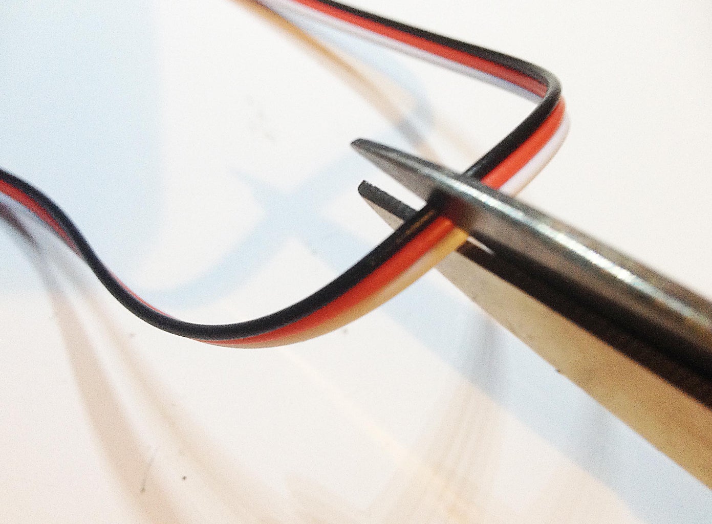
- This ammeter is very sensitive and it will fry instantly if wrongly connected. The ammeter has 4 wires, 2 thin and 2 thick wires. The two thin wires (black and red) are power input, black = negative, red= positive, nothing too complicated. This is the bit where you need to be careful: The 2 thick cables (black and white) are black= negative in to ammeter, white= negative out of ammeter. Make sure you connect the cables right. It may be a good idea to try the accuracy of the ammeter before mounting it to the box.
- The ammeter has a resistor shunt (or at least that’s what I think it is), on the front of the PCB, this shunt is coming out even more than the 7 Segment LEDs, making it impossible to mount on the box. To solve the issue what I did is desolder the resistor shunt and resolder it to the back of the PCB.
Do not connect the small black wire if you are powering the ammeter from the same source to be read like I did. Otherwise it will give you a wrong reading.
Step 6: Schematic and Soldering


Here is the schematic, it’s very simple really.
- Use servo wires for the potentiometers, and with electrical tape or some heat shrink cover the solders. The same is done with the LEDs. See the photo for the “polarity” of the LEDs on the PCB I used.
- After soldering everything, it’s time to fix the meters to the box. Secure them with hot glue, but not too much just in case you need to replace them in the future.
Step 7: Finish!


Everything just about fits in the box. I hope you enjoy reading this Instructable, I'll be happy to answer any questions.
See my other Instructables for cool projects like this one :)
If you like this Instructable please vote for it in the contest. Thank you very much! :)

Third Prize in the
Portable Workstations Contest


