

Introduction: Minimalist IoT Clock (using ESP8266, Adafruit.io, IFTTT, and Arduino IDE)

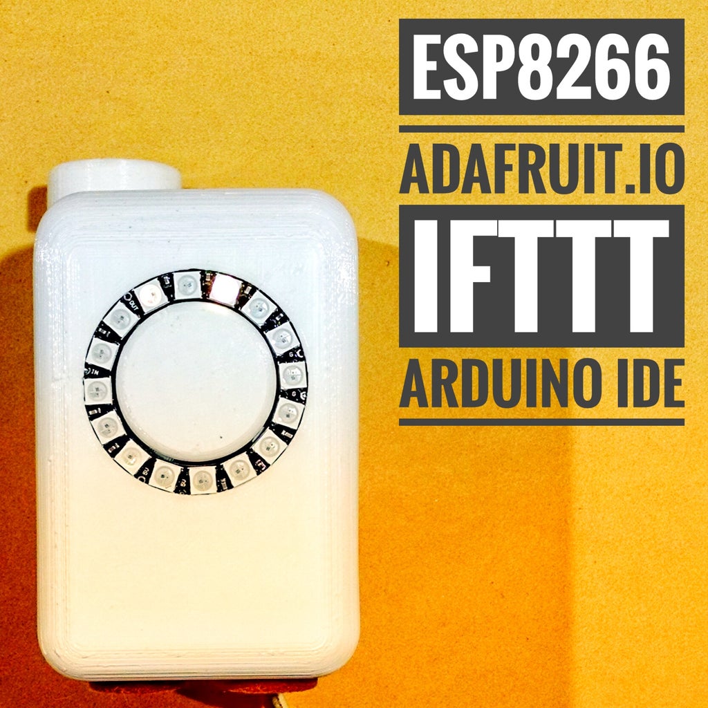


In this tutorial I show how you can make a minimalist clock synchronized with the internet. I tested it with two different ESP8266 based boards: Firebeetle and NodeMCU. The microcontroller gets current time from a Google server, and displays it on a NeoPixel LED ring. It also receives current weather data from WeatherUnderground, using IFTTT and Adafruit.io platforms, and change LEDs colors based on the weather condition.
It won't have a good resolution (due to the small number of LEDs), but it's a good way to practice your coding and electronic skills using a small number of components. I'll also be able to create a device that 'knows' current time, without the use of an external real time clock circuit, and that's able to 'sense' changes on the weather.
You might integrate it with other gadgets that already have an idle LED ring. It was designed for my IoT air freshner (https://www.instructables.com/id/IoT-Air-Freshner-with-NodeMCU-Arduino-IFTTT-and-Ad/), giving it a new functionality. You might do the same to other gadgets.
Some of the knowledges used here were based on Becky Stern awesome Internet of Things Class. It's highly recommended!
Part of the code was based on torntrousers comment on ESP8266 forum http://www.esp8266.com/viewtopic.php?f=29&t=6007&start=5. Thanks for helping the community!
Step 1: Tools and Materials


For this project I needed a small amount of materials:
- Solder wire. I needed it to solder some wires to the LED ring, and to solder the pins bar to my ESP8266 boards;
- ESP8266 dev board. There are several ESP8266 based boards. I tried two of them in this tutorial:
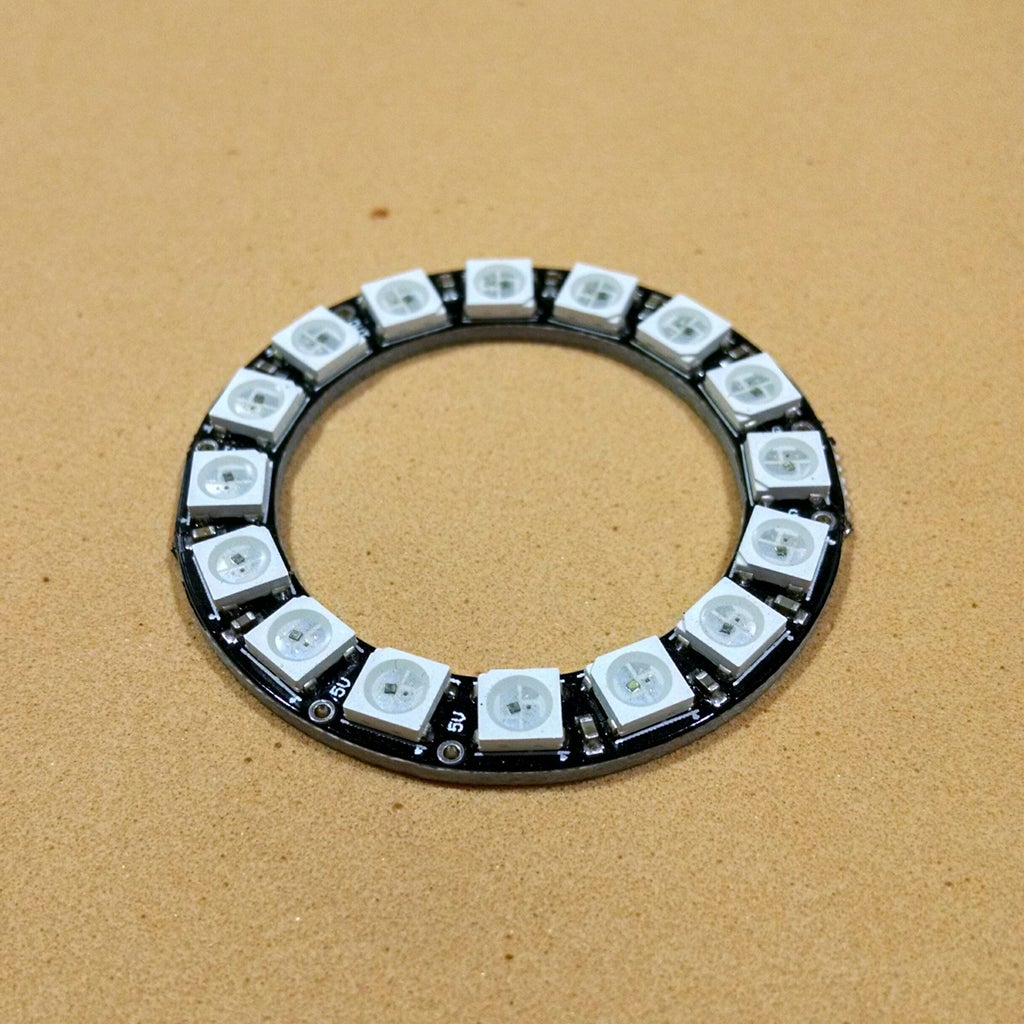
- NeoPixel 16 x WS2812 5050 RGB LED (link / link / link);
- MiniUSB cable, for the connection between the ESP8266 board and the computer (for uploading the code);
- 5V, USB charger (phone charger, for instance) for powering the circuit;
- 3 female-female jumper wires. I used it for the connection between the LED ring and the ESP8266 board.
The development board connects a given Wi-Fi network, and receives some data from Adafruit.io platform. A NeoPixel ring is used as a clock. It can also indicate the status of the gadget (if the Wi-fi connection was successful, for instance). The color of the LEDs will depend on the data received from an Adafruit.io feed. A 5V USB charger was used to power the control board and all the peripherals.
Once a 16 LEDs NeoPixel ring was used, the resolution for my clock was quite limited. The minimum division for the seconds LED is around 4 seconds. The minutes LED is only updated every 4 minutes. You can use a ring with more LEDs if you want a better resolution. There are versions with 24 LEDs (link / link), for instance. A 12 LED ring would also be a good choice for displaying the hours (link / link).
The links above are only a suggestion of where you can find the items used in this tutorial (and maybe support my future tutorials). Feel free to search for them elsewhere and buy at your favorite local or online store.
You can also design a 3D printed case for your clock. Did you know you can buy a Anet A8 for only $169.99? Click here and get yours!
Step 2: Preparing the NeoPixel Ring

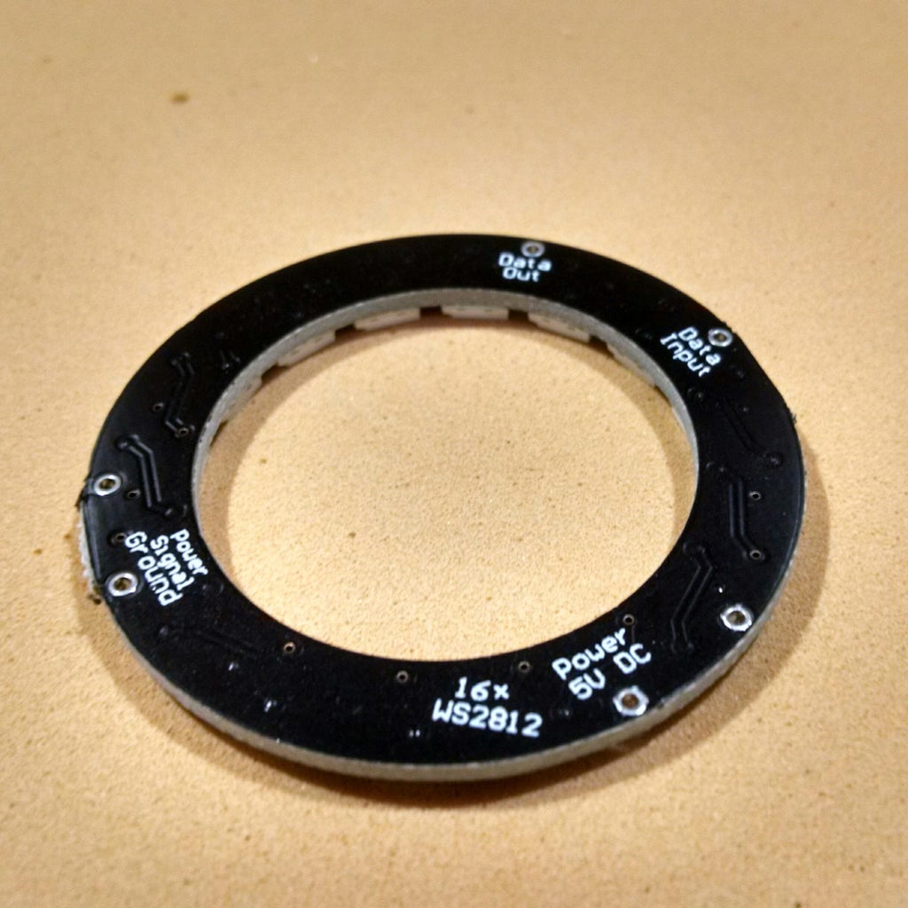
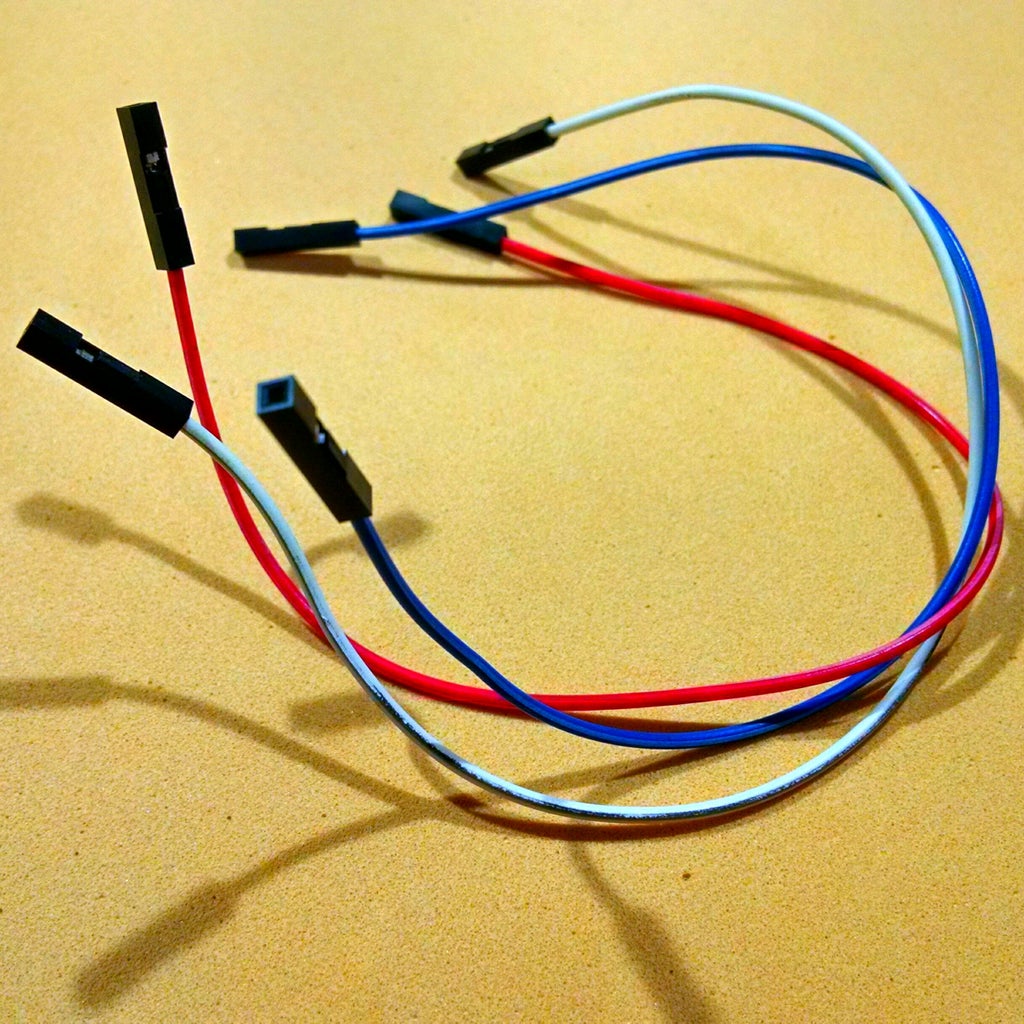

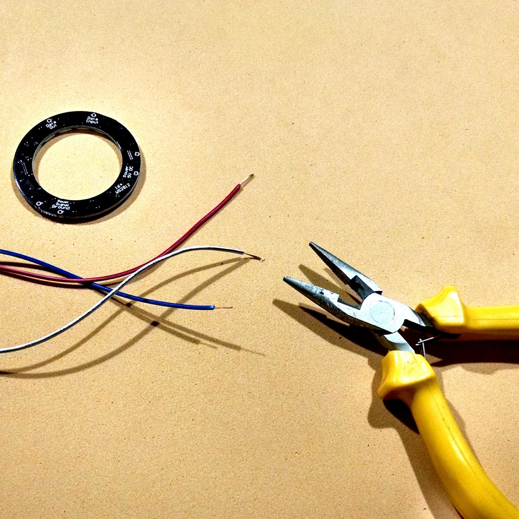
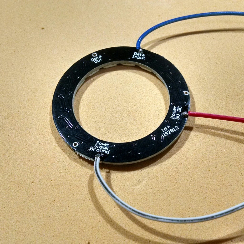

NeoPixel rings usually comes without wires connected to their terminals. This means you'll have to solder some wires for the connection of the LEDs to your microcontroller. For that I used three female-female jumpers. I cut one side of the jumper and soldered the wires in NeoPixel ring terminals. I kept the other end of each jumper with a female terminal, which I connected on my ESP8266 board.
- Red wire = 5V
- Black wire = GND
- Blue wire = Data input
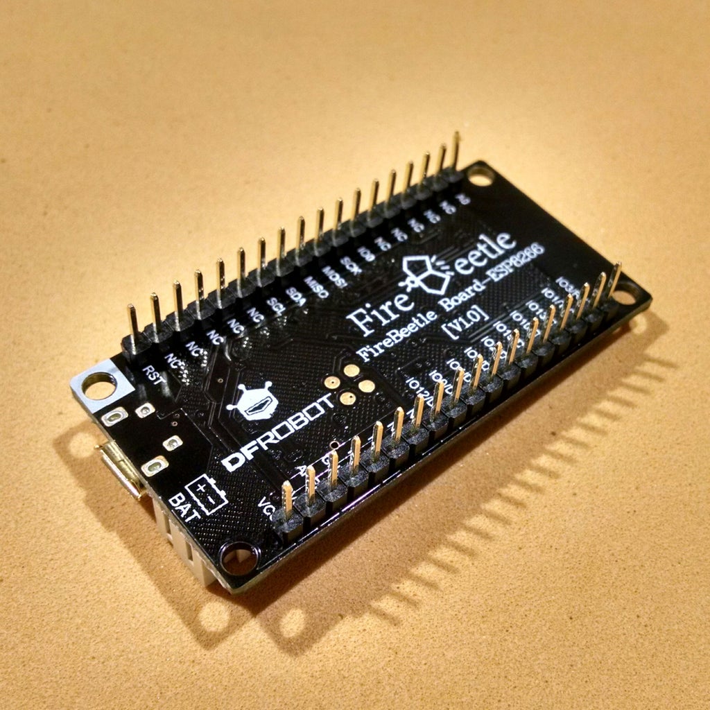
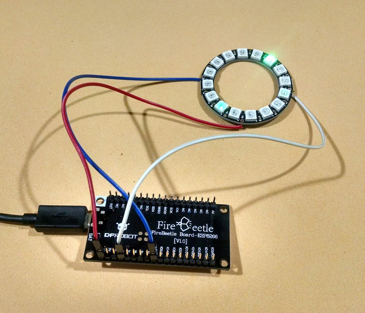
Step 3: Circuit With Firebeetle Board


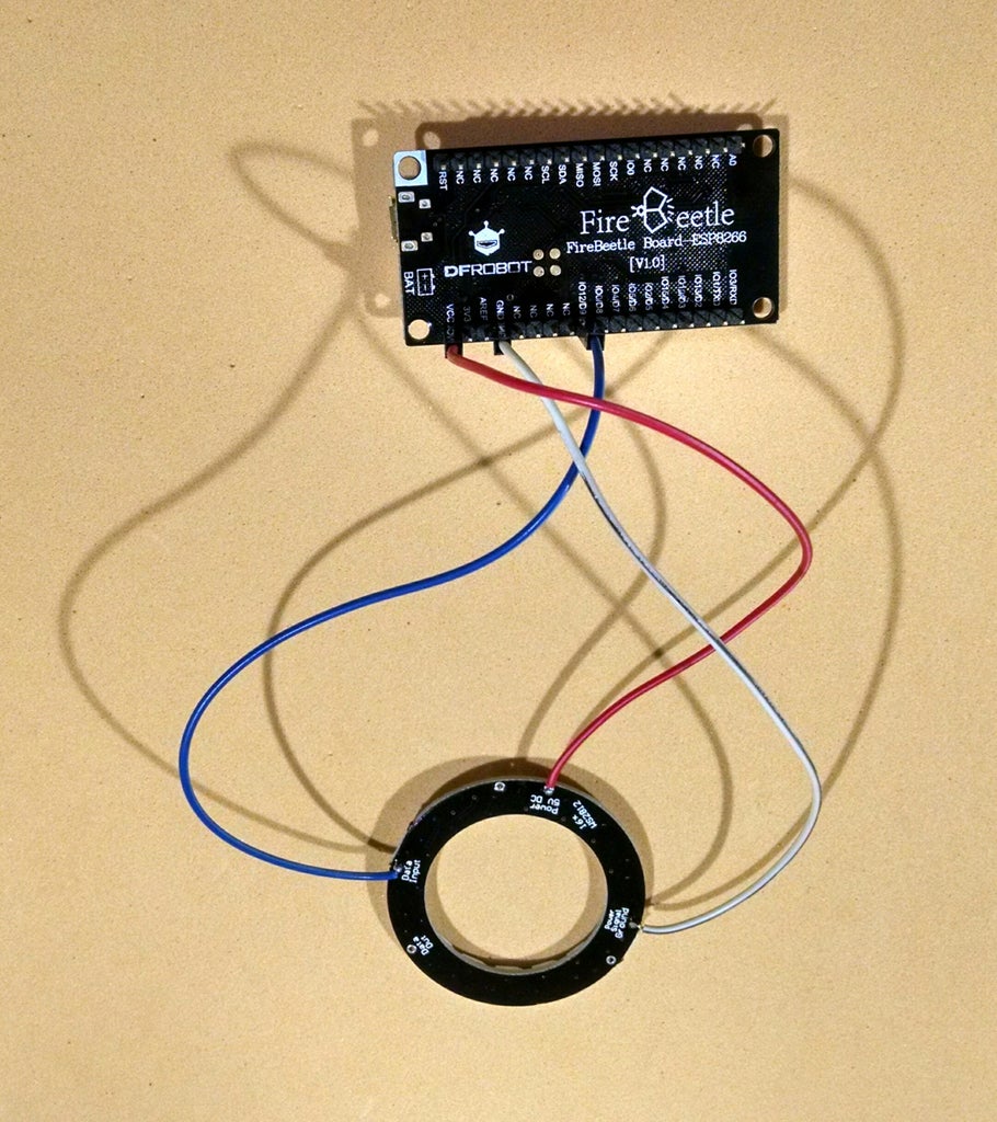


For this project I tried two different ESP8266 boards: Firebeetle and NodeMCU.
DFRobot FireBeetle is a low-power-consumption development board designed for Internet of Things. It has an integrated WiFi, TCP/IP, 32-bit MCU, 10-bit ADC and multiple interfaces such as HSPI, UART, PWM, I2C and I2S. Firebettle boards are compatible with Arduino IDE.
It has a connector for a Li-ion battery, which might be really useful! It has a great finishing too.
Once the NeoPixel was soldered, I connected the wires according to the schematics.
- NeoPixel 5V (red wire) => Firebeetle Vcc pin
- NeoPixel GND (black wire) => Firebeetle GND
- NeoPixel Data input (yellow wire) => Firebeetle GPIO 12 (pin D9)
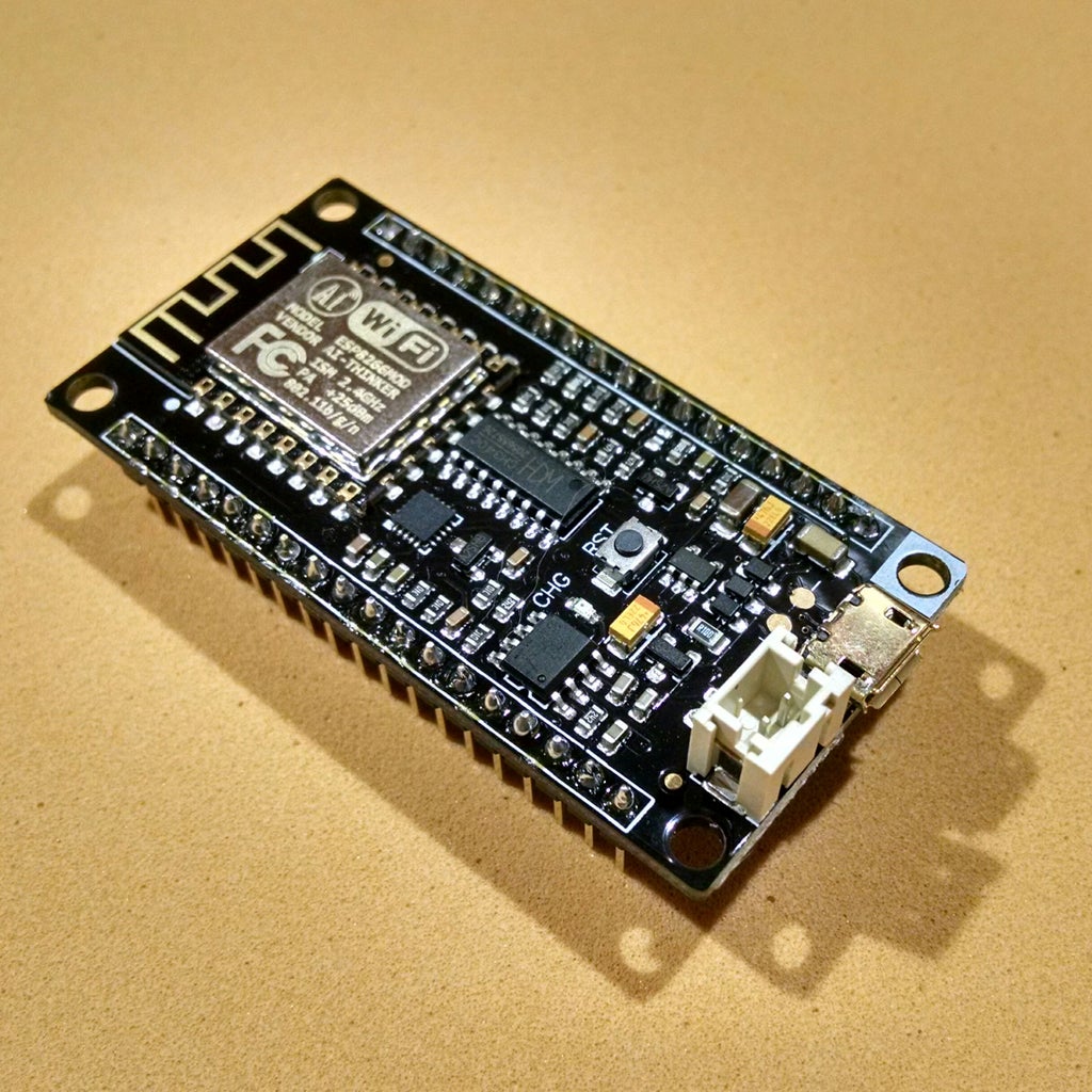
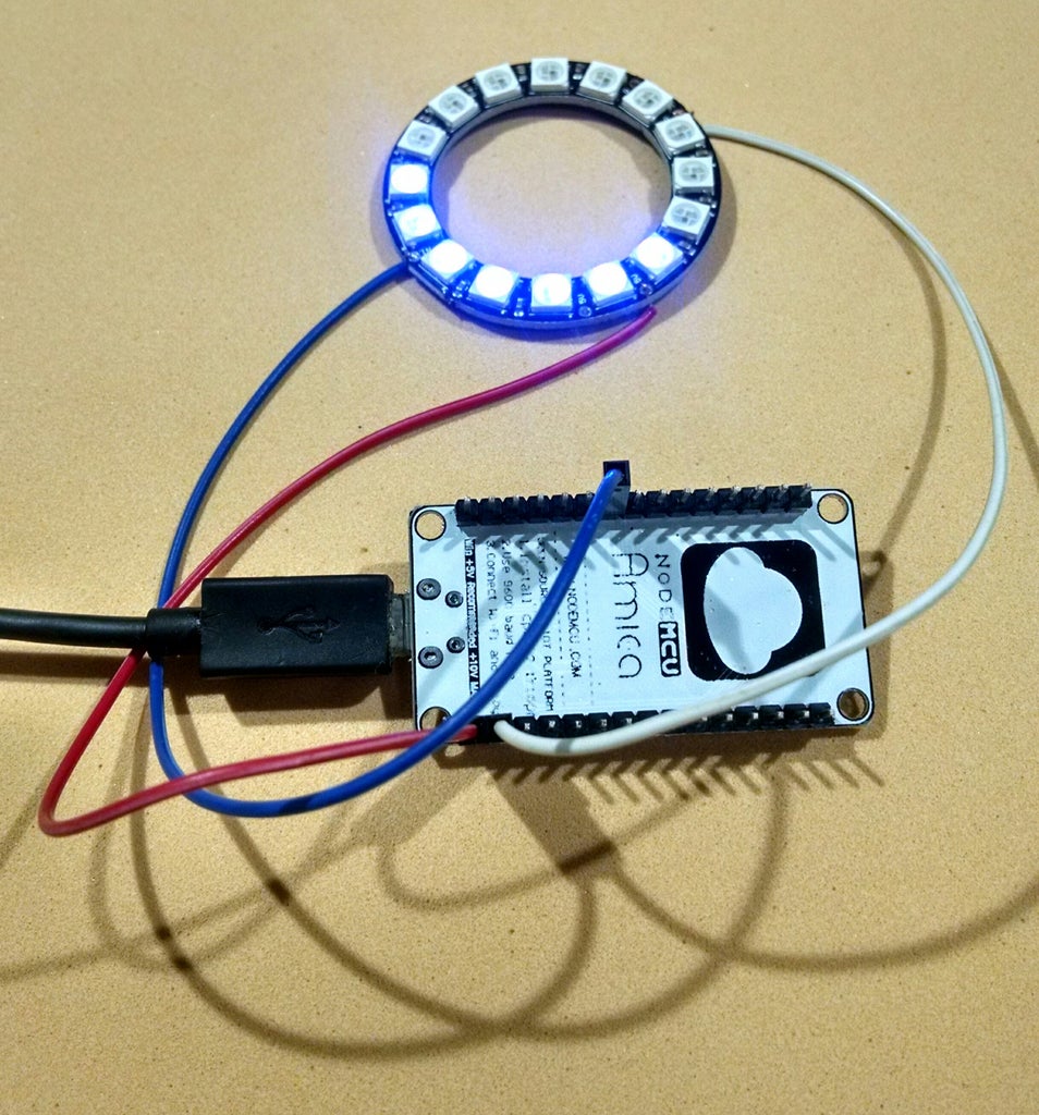
Step 4: Circuit With NodeMCU Board


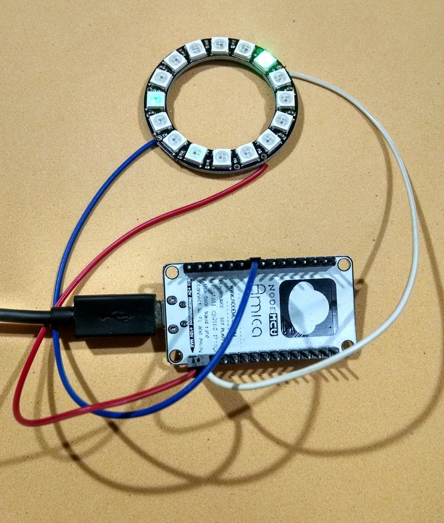

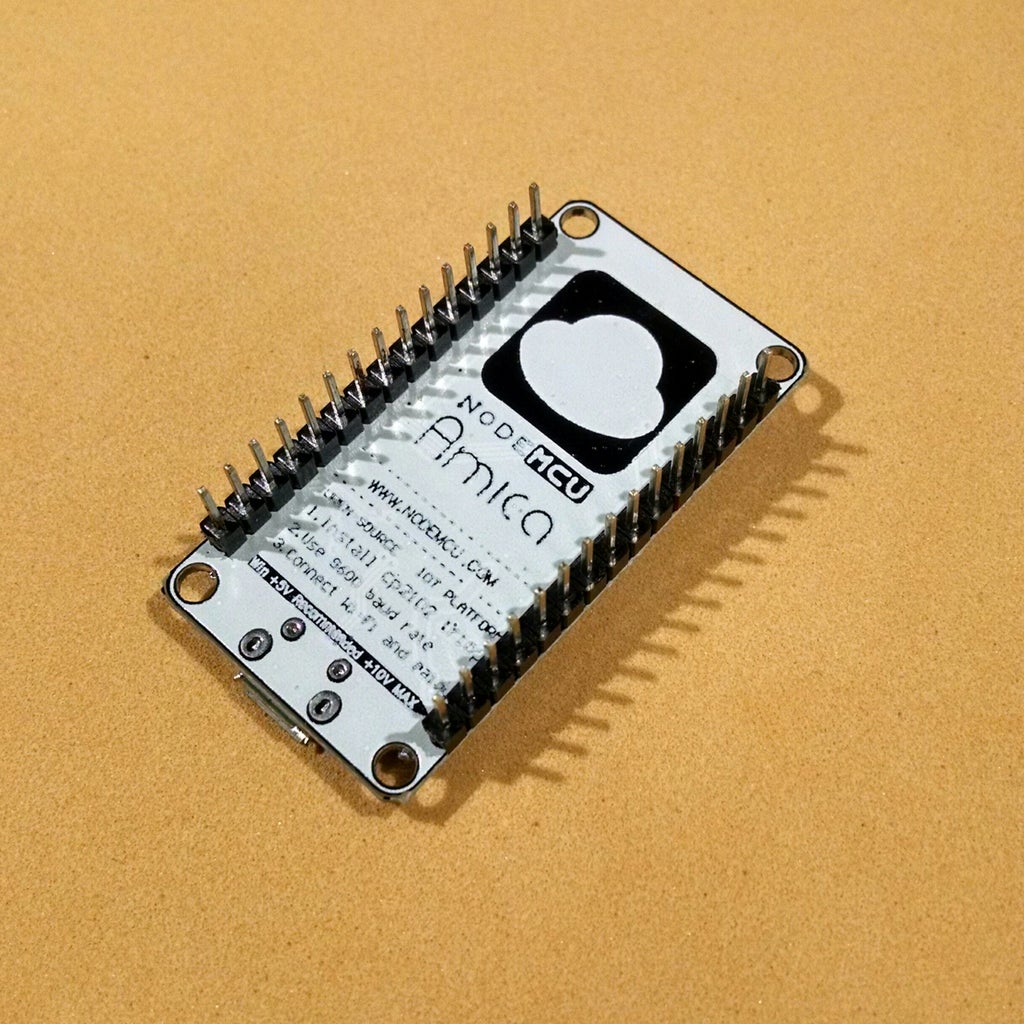

NodeMCU is an open source IoT platform, which runs on an ESP8266 Wi-Fi SoC from Espressif Systems. It's hardware is based on the ESP-12 module.
Once the NeoPixel was soldered, I connected the wires according to the schematics.
- NeoPixel 5V (red wire) => NodeMcu 3V3
- NeoPixel GND (black wire) => NodeMcu GND
- NeoPixel Data input (blue wire) => NodeMcu GPIO 12 (pin D6)
Step 5: Setup ESP8266 Board on Arduino IDE
For this project I used Arduino IDE for programming my ESP8266. It's the easier way if you've already used an Arduino before, and you won't need to learn a new programming language, like Python or Lua for instance.
If you've never done this before, first you'll have to add ESP8266 board support to the Arduino software.
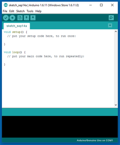
1. Download and install Arduino IDE latest version
You can find the latest version for Windows, Linux or MAC OSX on Arduino's website: https://www.arduino.cc/en/main/software
Download it for free, install it on your computer and launch it.
2. Adding ESP8266 board
Arduino IDE already comes with support to a lot of different boards: Arduino Nano, Mine, Uno, Mega, Yún, etc. Unfortunatly ESP8266 isn't by default among those suported development boards. So in order to upload your codes to a ESP8266 base board, you'll have to add its properties to Arduino's software first.
2.1. Firebeetle
- Navigate to File > Preferences (Ctrl + , on Windows OS);
- Add the following URL to Additional Boards Manager textbox (the one on the bottom of the Preferences window): https://raw.githubusercontent.com/DFRobot/FireBeetle-ESP8266/master/package_firebeetle8266_index.json
- If the text box wasn't blank, it means had already add other boards before on Arduino IDE before. Add a comma at the end of the previous URL and the one above.
- Hit "Ok" button and close the Preferences Window.
- Navigate for Tools > Board > Boards Manager for adding your adding your Firebeetle ESP8266 board.
- Type "Firebeetle-ESP8266" on the search text box, select "FireBeetle-ESP8266 by DFRobot" and install it.
Now your Arduino IDE will be ready to work with the Firebeetle ESP8266 development board.
2.2. NodeMCU
- Navigate to File > Preferences (Ctrl + , on Windows OS);
- Add the following URL to Additional Boards Manager textbox (the one on the bottom of the Preferences window): http://arduino.esp8266.com/stable/package_esp8266com_index.json
- If the text box wasn't blank, it means had already add other boards before on Arduino IDE before. Add a comma at the end of the previous URL and the one above.
- Hit "Ok" button and close the Preferences Window.
- Navigate for Tools > Board > Boards Manager for adding your ESP8266 board.
- Type "ESP8266" on the search text box, select "esp8266 by ESP8266 Community" and install it.
Now your Arduino IDE will be ready to work with a lot of ESP8266 based development boards, like the generic ESP8266, NodeMcu (which I used in this tutorial), Adafruit Huzzah, Sparkfun Thing, WeMos, etc.
3. Adding the libraries
The following libraries will be used for our Arduino code. Download the following libraries:
- Adafruit NeoPixel library (https://github.com/adafruit/Adafruit_NeoPixel)
- Arduino http client library (https://github.com/arduino-libraries/ArduinoHttpClient)
- Arduino IO library (https://github.com/adafruit/Adafruit_IO_Arduino)
- Adafruit MQTT library (https://github.com/adafruit/Adafruit_MQTT_Library)
Navigate to Sketch -> Include Library -> Manage Libraries... on your Arduino IDE and add the libraries above.
Step 6: Adafruit.IO Configuration


There are a lot of datalogging services available for communicating a microcontroller to the web. With those services you can upload/download data to/from the cloud, and do a lot of cool stuff. Take a look on my tutorial on how to use an Arduino + ESP8266 to send data from a mini-weather station for Thinkgspeak for instance.
Adafruit.IO is one of those free services. It's really easy to use and promises to bring internet of things to everyone!
Create Adafruit IO Web Feed
- Sign in at https://io.adafruit.com/
- Under Feeds > Create a new Feed add a new feed named 'precipitation'. It will create a database, and we will use it store weather forecast data.
- Copy your Adafruit.IO key. Navigate for Settings > View AIO key and copy the active key code. You'll need it for your Arduino (NodeMCU) code on next steps.
Step 7: IFTTT Configuration and Applet Creation


IFTTT is a free platform that helps you connects apps and devices. You can use it to connect your smartphone with other gadgets, or to share data between your favourite webservices (like Google, Facebook, Twitter, Instragram, etc.) and other physical devices, for instance. And the best part is that it's really easy to use!
IFTTT uses a 'if this then that' logic, where 'this' represents a service that will trigger a given action given by 'that'. This way you create small applets connecting webservices and devices. For this project, a WeatherUnderground applet was designed.
- First you'll have to sign in at: https://ifttt.com/.
- On the website, navigate to New Applet (click the arrow button next to your login to access the menu).
- Click +This;
- Type 'Weather Undergroung' on Seach service text box and select Weather Underground > If current condition changes to. This Trigger monitors changes in the current weather condition. When one of those conditions is met the Trigger fires. Four weather conditions are supported: Rain, Snow, Cloudy, Clear. You'll have to create an applet for each one of those conditions.
- Choose +That;Type 'adafruit' and select Adafruit > Send data to Adafruit IO. This will send data to a feed in your Adafruit IO account whenever the trigger you configured previously (+This) is activated;
- Configure Feed name as 'precipitation' and Data to save as 'Rain', 'Snow', 'Cloudy' and 'Clear' (one for each applet).
- Finish your applet and turn it on.
Step 8: ESP8266 Code
After the triggers were set, it's time to work on the ESP8266 code. Download it and open the .ino file on Arduino IDE.
You'll have to update user name, io key, Wi-Fi id and password before uploading the code for you ESP8266. Visit adafruit.io, log into your account and copy the io key (as it was described in previous steps).
For uploading your code, select the NodeMCU 0.9 (ESP-12 Module) (if you're using a NodeMCU) with 11520 kbps upload speed. Plug NodeMCU to your computer's USB port and upload the code. It will take a while (much more than compliling and uploading a sketch for an Arduino... be patient...). Now it's a good time for you to give a like on this instructable while you wait! :D
After the upload was complete, unplug the USB cable, and power your circuit from a USB charger.
The gadget will connect a given Wi-Fi network, check current time from a Google server, and start working as a clock. Once every minute it will check the current time from the server again, and update its internal clock. LEDs will be updated once every three seconds, displaying the hours, minutes and seconds.
A new command is received on Arduino.IO feed whenever current weather changes. When a message is received, the IoT clock will change LEDs colors according to the weather condition (red = rain, yellow = cloudy, green = clear, blue = snow).
Code explained:
For the Adafruit IO configuration, you'll have to replace the user name (XXXXXXXXXX) and io key (YYYYYYYYY). Visit adafruit.io, log into your account and copy the io key (as it was described earlier).
/************************ Adafruit IO Configuration *******************************/
// visit io.adafruit.com if you need to create an account, or if you need your Adafruit IO key.
#define IO_USERNAME    "XXXXXXXXXX"
#define IO_KEY         "YYYYYYYYY"
You'll also have to specify the SSID and password for your Wi-Fi router. Replace WWWWWWWWWW and ZZZZZZZZZZ according to your Wi-Fi router configuration.
******************************* WIFI Configuration **************************************/
#define WIFI_SSID       "WWWWWWWWWW"
#define WIFI_PASS       "ZZZZZZZZZZ"
#include "AdafruitIO_WiFi.h"
AdafruitIO_WiFi io(IO_USERNAME, IO_KEY, WIFI_SSID, WIFI_PASS);
The following libraries will be used (as described in previous steps). You'll need to add them on the Arduino ide before compiling the code.
/************************ Main Program Starts Here *******************************/
#include <ESP8266WiFi.h>
#include <AdafruitIO.h>
#include <Adafruit_MQTT.h>
#include <ArduinoHttpClient.h>
#include <Adafruit_NeoPixel.h>
Before setup, the LED ring parameters are configured and global variables are defined. If your LED ring is installed somewhere and you can't rotate it, you clock will be misaligned, and it won't show the hours correctly. Change the OFFSET value to compensate that misalignement.
Also change the TIMEZONE value according to your current location.
#define PIXELS_PIN 15   // Pin connected to the NeoPixel data input
#define NUM_LEDS   16   // Number of NeoPixels
#define BRIGHTNESS 30   // Brightness of the LEDs<br>
#define PIXEL_TYPE NEO_GRB + NEO_KHZ800   // Type of the NeoPixels (see strandtest example).
Adafruit_NeoPixel ring = Adafruit_NeoPixel(NUM_LEDS, PIXELS_PIN, PIXEL_TYPE);// + NEO_KHZ800);

AdafruitIO_Feed *command = io.feed("iot-air-freshner-command"); // set up the 'command' feed

String TimeDate = ""; // Variable used to store the data received from the server<br>int hours; // Current hour<br>int minutes; // Current minute<br>int seconds; // Current second
int seconds0; // Last time the LEDs were updated
String weather = "Clear"; // Current weather condition
#define OFFSET  2 // LED offset. It's used to compensate for misalignment between the LED ring and the 12 o'clock position
#define TIMEZONE  3 // Current time zone. Used for correction of server time
During the setup, the NodeMCU will initialize the LEDs (turn then off), start the serial communication port and connect to Adafruit.io. An animation will be displayed while it attemps to connect the Wi-Fi network.
If the connection is successful, the ESP8622 will ask a server for the current time using getTime() function.
void setup() {
  // Initialize all pixels to 'off'
  ring.setBrightness(BRIGHTNESS);
  ring.begin();
  ring.show();

  // Start the serial connection
  Serial.begin(115200);

  // Enable wathchdog timer. The ESP8266 after 5 seconds if something goes wrong
  ESP.wdtEnable(5000);

  // connect to io.adafruit.com
  Serial.print("Connecting to Adafruit IO");
  io.connect();

  // set up a message handler for the 'command' feed.
  // the handleMessage function (defined below)
  // will be called whenever a message is
  // received from adafruit io.
  command->onMessage(handleMessage);

  // wait for a connection
  int i = NUM_LEDS - 1;
  int color = 255;
  // animate LEDs while waiting for connection
  while(io.status() < AIO_CONNECTED) {
    Serial.print(".");
    ring.setPixelColor(i, 0, 0, color);
    ring.show();
    i = i - 1;
    if (i < 0) {
      if (color == 255) {
        color = 0;
      }
      else {
        color = 255;
      }
      i = NUM_LEDS - 1;
    }
    delay(50);
  }
  lightPixels(ring.Color(0, 0, 0, 0)); // reset all pixels to off when connected

  // we are connected
  Serial.println();
  Serial.println(io.statusText());

  // get current time from server
  getTime();

  seconds0 = millis();
}
Main loop is quite simple. It verifies if there is incoming data from Adafruit.io. It also updates the LEDs every 3 seconds, and check server clock every 60 seconds using getTime() function.
void loop() {

  // io.run(); is required for all sketches.
  // it should always be present at the top of your loop
  // function. it keeps the client connected to
  // io.adafruit.com, and processes any incoming data.
  io.run();

  // update LED ring every 3 seconds
  if ((millis() - seconds0) > 3000) {
    seconds = seconds + 3;

    // synchronize with the server every minute
    if (seconds > 59) {
      getTime();
    }

    // display clock
    showTime();
    seconds0 = millis();
  }
}
handleMessage function is called when a new message is received. This function reads the last data received on a given Adafruit.io feed, check if one of the known command strings was received ('Rain', 'Clear', 'Cloudy' or 'Snow'), and store current weather condition on a global variables.// this function is called whenever a message
// is received from Adafruit IO. it was attached to
// the feed in the setup() function above.
void handleMessage(AdafruitIO_Data *data) {
lightPixels(ring.Color(0, 0, 0, 0)); // reset all pixels to off when new info is received
String commandStr = data->toString(); // store the incoming commands in a string
Serial.print("received <- ");
Serial.println(commandStr);
// These if statements compare the incoming weather variable to the stored conditions, and control the NeoPixels accordingly.
// if weather has changed
if (commandStr.equalsIgnoreCase("Rain")){
Serial.println("It's raining!");
weather = "Rain";
}
if (commandStr.equalsIgnoreCase("Clear")){
Serial.println("It's clear!");
weather = "Clear";
}
if (commandStr.equalsIgnoreCase("Cloudy")){
Serial.println("It's cloudy!");
weather = "Cloudy";
}
if (commandStr.equalsIgnoreCase("Snow")){
Serial.println("Snow!");
weather = "Snow";
}
}getTime() funcion connects to Google and gets cutrrent time. It receives a string with current day of the week, day of the month, month, year, hour, minute, and second. The code extracts only the hours, minutes and seconds from that string, convert them to integers and save on some global variables.
Eventually the ESP8266 will fail to receive the data from the server (if connetion was lost, or if it takes too long to connect, for instance). If no answer was received within 0.5 seconds, it will stop waiting, move on, and try again after one minute.
Part of this code was based on torntrousers solution, found on ESP8266 forum: http://www.esp8266.com/viewtopic.php?f=29&t=6007&s.... Thanks for the help!
//Get current time Google server
void getTime() {

  WiFiClient client;
  while (!!!client.connect("google.com", 80)) {
    Serial.println("connection failed, retrying...");
  }

  client.print("HEAD / HTTP/1.1\r\n\r\n");

  delay(500); //wait a few milisseconds for incoming message

   //if there is an incoming message
   if(client.available()){
     while(client.available()){
       if (client.read() == '\n') {
         if (client.read() == 'D') {
           if (client.read() == 'a') {
             if (client.read() == 't') {
               if (client.read() == 'e') {
                 if (client.read() == ':') {
                   client.read();
                   String theDate = client.readStringUntil('\r');
                   client.stop();

                   TimeDate = theDate.substring(7);
                   Serial.println(TimeDate);
                   // time starts at pos 14
                   String strCurrentHour = theDate.substring(17,19);
                   String strCurrentMinute = theDate.substring(20,22);
                   String strCurrentSecond = theDate.substring(23,25);
                   Serial.println(strCurrentHour);
                   Serial.println(strCurrentMinute);
                   Serial.println(strCurrentSecond);
                   hours = strCurrentHour.toInt();
                   minutes = strCurrentMinute.toInt();
                   seconds = strCurrentSecond.toInt();
                 }
               }
             }
           }
         }
       }
     }
   }
   //if no message was received (an issue with the Wi-Fi connection, for instance)
   else{
     seconds = 0;
     minutes += 1;
     if (minutes > 59) {
       minutes = 0;
       hours += 1;
       if (hours > 11) {
         hours = 0;
       }
     }
   }
}
After current time was calculated, it's time time display it on the LED ring. showTime() function does this job.
First it will select the color of the LEDs based on current weather condition. The color of the LEDs is based on three components: red, green and blue LEDs. I used the following codification:
- Rain: red = 1, green = 0, blue = 0; (RED)
- Clear: red = 0, green = 1, blue = 0; (GREEN)
- Cloudy: red = 1, green = 1, blue = 0; (YELLOW)
- Show: red = 0, green = 0, blue = 1; (BLUE)
It will then map hours, minutes and seconds into LED ring positions. As described earlier, and OFFSET was introduced for compensate ring rotation, and TIMEZONE for the calculation of the hours at your current location.
ring.setPixelColor() function is used for turning on/off a given LED. Notice I used a multiplier for making the hours LED brighter (255), followed by minutes (64) and seconds (10). This way, one can identify what does each LED on the clock means (once their color will only indicate weater condition).
//Update LED rings clock
void showTime(){

  // reset all pixels to off when connected
  lightPixels(ring.Color(0, 0, 0, 0));
  int pixelR = 0;
  int pixelG = 0;
  int pixelB = 0;

  // choose color according to current weather condition
  // hours, minutes, and seconds LEDs will have the same colors
  // hours will be brighter, while seconds will be more faint
  if (weather == "Rain") {
    pixelR = 1;
  }
  if (weather == "Clear") {
    pixelG = 1;
  }
  if (weather == "Cloudy") {
    pixelR = 1;
    pixelG = 1;
  }
  if (weather == "Snow") {
    pixelB = 1;
  }

  // map the seconds to the LED ring
  int secondsdisplay = map(seconds, 0, 60, NUM_LEDS, 0);
  secondsdisplay = secondsdisplay - OFFSET;
  if (secondsdisplay < 0) {
    secondsdisplay = secondsdisplay + NUM_LEDS;
  }
  ring.setPixelColor(secondsdisplay, 10*pixelR, 10*pixelG, 10*pixelB);

  // map the minutes to the LED ring
  int minutesdisplay = map(minutes, 0, 60, NUM_LEDS, 0);
  minutesdisplay = minutesdisplay - OFFSET;
  if (minutesdisplay < 0) {
    minutesdisplay = minutesdisplay + NUM_LEDS;
  }
  ring.setPixelColor(minutesdisplay, 64*pixelR, 64*pixelG, 64*pixelB);

  // map the hours to the LED ring
  int hoursdisplay;
  hoursdisplay = hours - TIMEZONE;
  if (hoursdisplay < 0) {
    hoursdisplay += 12;
  }
  if (hoursdisplay > 12) {
    hoursdisplay = hoursdisplay - 12;
  }

  hoursdisplay = map(hoursdisplay, 0, 12, NUM_LEDS, 0);
  hoursdisplay = hoursdisplay - OFFSET;
  if (hoursdisplay < 0) {
      hoursdisplay = hoursdisplay + NUM_LEDS;
  }
  ring.setPixelColor(hoursdisplay, 255*pixelR, 255*pixelG, 255*pixelB);

  // update LEDs
  ring.show();
}
Attachments

Step 9: Testing


Upload the code, plug the ESP8266 on a power source and it's done!
It will try to connect the Wi-Fi network, and periodically read current time and weather conditions. You can force a change on the current weather condition to see if the color of the LED is changing correctly. On your Adafruit.IO feed, add a new data point with one of the possible values ('Snow', 'Cloud', 'Clear' or 'Rain'). The ESP8266 is supposed to receive the new weather condition and change the LED colors.
Always have in mind that this is an experimental prototype, and might be used with caution!
You can now design a nice case for your minimalistic clock and start using it! A 3d printed case might be a good solution. There are lots of inexpensive and good 3D printers on the market. You can find the Anycubic I3 mega printer for only $343.99 at http://bit.ly/2FT9ve0!
I've added the clock described in this tutorial to my award winning IoT air freshener. Check it out! :D
If you liked this tutorial, please click the 'like' button and share it with your friends! :D
Step 10: Final Considerations
If you still don't follow my tutorials, take a look at those other projects in which I explain a little bit about internet of things, robotics and 3D printing. I hope you enjoy them too!
https://www.instructables.com/id/IoT-Wallet-smart-...
https://www.instructables.com/id/IoT-Air-Freshner-...
https://www.instructables.com/id/Minimalist-IoT-Cl...
https://www.instructables.com/id/IoT-Air-Freshner-...
https://www.instructables.com/id/Nunchuk-Controll...
Liked any of my projects? Please consider supporting my future projects with a small Bitcoin donation! :D
BTC Deposit Address: 1FiWFYSjRaL7sLdr5wr6h86QkMA6pQxkXJ

Participated in the
Pocket-Sized Contest

Participated in the
Pro Tips Challenge


