

Introduction: Modern Logic Probe


Modern Logic Probe was designed to measure 0´s and 1´s logics and for working with a voltage from 5V to 12VDC. This project was based in an LM358 and a common cathode RG LED to its monitorial. The Modern Logic Probe is capable of being adjusted to 0V with help of a couple of trimmers of 5K for turning off the RG LED. Using the project, the result is a RED led turns on when a ´zero logic´ is applied or a Green LED turns on when an ´one logic´ is applied.
What you will need:
Soldering Iron & Solder Roll
Wire Cutter & Stripper
Drill & Drill bits of 3/16" & 1/4"
1 Hex nut of 5mm
Plastic Color Tape
Step 1: Bill of Materials


1 LM358N
1 Socket IC-8 Pin
1 Case ABS Speedy 3.125x2x.875
1 Prototype Builder 1.6" X2.7" PCB
2 Alligator Clip Test Leads: Red & Black
1 Test Lead with Screw On Tip, Red or Black
2 1/2 Watt 3/8" Square Trimming Potentiometer 5k Ohm
1 5mm Water Clear RGB LED - Common Ground
1 Led Mounting Hardware T1-3/4 Clear Standard
1 400 VOLT 1 AMP DO-41 SILICON RECTIFIER DIODE (1N4004)
1 Resistor Carbon Film 12K Ohm 1/4 Watt 5%
2 Resistor Carbon Film 120 Ohm 1/4 Watt 5%
1 Resistor Carbon Film 2.7K Ohm 1/4 Watt 5%
1 Resistor Carbon Film 3.3M Ohm 1/4 Watt 5%
1 HEAT SHRINK TUBING,FIT-221B-1/16-BLACK,4 FEET,BLACK POLYOLEFIN
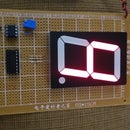
Step 2: Diagram 1

In this diagram 1, you can see a LED lit and its light is red because a ´zero´ logic is being applied in the point of probe (connected to pins: 3 & 6) of your project. Also note that the LED is a type of common ground connection, so you can simply connect to their respective resistors so that you can monitor the result either ´zero´ or ´one´. According to the project, you will connect pin 4 & diode´s positive terminal to GND & positive terminal of this project (alligator clips black & red) respectively while diode´s negative terminal to pin 8 from LM358.
Step 3: Diagram 2

In this diagram 2, you can see a LED lit and its light is green because an ´one´ logic is being applied in the point of probe (connected to pins: 3 & 6) of your project. Also note that the LED is a type of common ground connection, so you can simply connect to their respective resistors (checking colors green and red to pins 1 & 7 respectively) so that you can monitor the result either ´zero´ or ´one´. According to the project, you will connect pin 4 & diode´s positive terminal to GND & positive terminal of this project (alligator clips black & red) respectively while diode´s negative terminal to pin 8 from LM358. You will besides connect to pins: 3 & 6 a resistor of 3.3 M Ohms while its terminal remaining to a resistor of 12K and trimmer of 5K. Then you should connect the terminal remaining of 12K resistor to diode´s positive terminal and 2.7K resistor while the terminal remaining of 2.7K to the other trimmer of 5K. Now, observe that the middle terminal of each trimmer of 5K should be connected to the pins: 1 & 5 where the first has connected a resistor of 2.7K while the second has both a resistor of 12K and other of 3.3MOhms, and without forgetting that you should connect both terminal remaining of the two trimmer of 5K to GND.
Step 4: Point of Probe 1


For making a point of probe, you can use a test lead with screw in the bottom and close to the wire of connection. Then you can just cut about 1" or 2" of wire by measuring from the point of connection to 1 or 2 inches of wire.
Step 5: Point of Probe 2


Once you cut the wire and without plastic insulation in your prospective point of probe, you will also need a hex nut of 5mm.
Step 6: Enclosure 1


Taking the ABS plastic enclosure, do a hole by using a drill bit of 3/16" for manipulating the rotary drill as many as necessary until you can insert the point of probe perfectly.
Step 7: Enclosure 2


Now, install the point of probe by using the hex nut of 5mm.
Step 8: Enclosure 3

In the part of the plastic enclosure showed in the photo, do a hole by using a drill bit of 1/4" to install the LED socket later.
Step 9: Enclosure 4

Now, install the LED socket.
Step 10: RGB LED to RG LED


So that the RGB LED becomes a RG LED, it´s necessary to cut the blue terminal of the RGB LED.
Step 11: Enclosure 5


Once installed the LED socket, insert the RG LED prepared in the previous step. In this step, you can use heat shrink tubing of 1/16" like insulation for both point of probe terminal and LED terminals.
Step 12: Alligator Clips


To prepare the alligator clips, you can use alligator clip test leads by taking one red and one black. With these alligator clips in your hands, you should cut them either in two parts or 3/4 according to your convenience.
Step 13: Enclosure 6


Now, take your ABS plastic enclosure and do a hole by using drill bit of 3/16" in the opposite side of the other hole where you installed the point of probe.
Step 14: Enclosure 7


In the hole done previously, install the alligator clips: red & black by passing the wires through the hole by doing a knot for supporting them inside of the enclosure.
Step 15: Installing Components 1


Taking the PCB, install the two trimmers of 5K and the IC socket of 8 pins.
Step 16: Installing Components 2


In this step, install the resistors of 12K, 2.7K, 3.3M Ohms and the diode 1N4004.
Step 17: Installing Components 3


For doing connections to the trimmers of 5K, I´m using green, brown and white wire. Note that you should check the project´s diagram constantly to avoid errors.
Step 18: Installing Components 4

Now, install the two resistors of 120 Ohms.
Step 19: Drawing the Wires for Doing Connections 1


Complete the connections to GND and draw a red and other green wire from the resistors of 120 Ohms to be connected to the red & green LED terminal respectively.
Step 20: Drawing the Wires for Doing Connections 2


Now, draw a black wire for being connected to the common ground of your LED installed previously, and you should also draw a yellow wire between the pins: 3 & 6 from the IC socket to be connected later to the point of probe. Finally, draw a couple of wires from the positive and negative terminal of this kit so that you can use them like connection to red and black alligator clip terminal respectively.
Step 21: Doing Connections 1


In this step, connect the three terminals of the RG LED by using its respective color wire for each LED color terminal. That is, green, black & red wire should be connected to green, common ground and red LED terminal respectively while the yellow wire should be connected to the point of probe. Note that I´m using color tape to identify each connection that obviously it´s optional but you can use them if you want.
Step 22: Doing Connections 2


For ending the connections, you should join GND and positive terminal of your project to the black & red alligator clip terminal respectively. In these terminals, I used color tape black and red to identify them.
Step 23: Adjusting the Project


In this step, you should adjust the project by manipulating the trimmers of 5K. That is, only adjust a trimmer by using a screwdriver until the LED is lit and no more so that you can obtain a red LED lit when a ´zero´ logic is applied. Then just adjust the other trimmer by using a screwdriver until the LED is lit and no more so that you can obtain a green LED lit when an ´one´ logic is applied. Once adjusted, until your project works correctly, you can close the box by using the srews included in this enclosure.
Step 24: Completing the Project


Once closed the plastic box of your project, you can see its look and use it for checking your logic circuits that you do since now.
Step 25: Checking the Project 1


For checking if the project functions correctly, you have to use it. The suggestion is that this kit be utilized for checking a ´0´ logic and observe the color of light lit: in this case, it should be red color. Now, a fast way would be to take any circuit that you already have done and if it works with a voltage from 5V to 12VDC then you can check your project by connecting the black & red alligator clips to GND & Vcc respectively where you will check a ´zero´ logic on GND of your own project.
Step 26: Checking the Project 2


For checking if the project functions correctly, you have to use it. The suggestion is that this kit be utilized for checking a ´1´ logic and observe the color of light lit: in this case, it should be green color. Now, a fast way would be to take any circuit that you already have done and if it works with a voltage from 5V to 12VDC then you can check your project by connecting the black & red alligator clips to GND & Vcc respectively where you will check an ´one´ logic on Vcc of your own project.


