

Introduction: Monitor Dress - Connect Heart Signals to the IoT


The Monitor Dress is an experiment in researching different ways of digitalizing the wearer’s heart activity as well as processing the data.
Three electrodes inside the dress measure the electrical signals running through the wearer’s body. Those analog impulses, which emanate from the muscle activity of the heart, are converted to digital signals. The microcontroller then lights up a circle of LEDs in the front of the dress, flashing purple with every heartbeat. The microcontroller also sends the data over a wireless network for other uses. The data sent over the wireless network is picked up by a computer, which is monitoring the data in order to animate it. The electrical signals of the heart are now visible on the display as well as the dress itself.
The Monitor Dress creates a seamless interface between the human body, garment and electronic components – digitalizing and recording our transient biosignals.
Step 1: Design and Circuit Overview


The top piece of the dress is made of black and clear acrylic pieces - cut with an laser cutter. A NeoPixel ring is glued underneath the clear acrylic circle in the middle. The wires run behind the top piece to a fabric strip which is attached to the top piece at the back of the dress. The fabric strip connects to the little pocket which holds the microcontroller, heart rate monitor and battery. Three e-textile electrodes are sewn into the lining of the dress. The wires connecting the electrodes and microcontroller run between two layers of fabric.
Step 2: Supplies:
Materials:
- Fabric
- Zipper
- Wires
- Heat Shrink
- 1/8" Black Acrylic
- 1/8" Diffused Acrylic
- NeoPixel Ring (24 LEDs) (Adafruit)
- Photon (Particle)
- Heart Rate Monitor (Sparkfun)
- Biomedial Sensor Pads (Sparkfun)
- Sensor Cable (Sparkfun)
- Conductive Fabric (Sparkfun or Adafruit)
- 5 Button Snaps
- Perma-Proto Board (Adafruit)
- Female + Male Jumper Wires
- Heat Shrink
- 5V Power Bank (Amazon)
Tools:
- Scissors
- Needle
- Thread
- Tweezers
- Soldering Iron
- Solder
- Hot Glue
- Heat Gun
- Sewing Machine
- Laser Cutter
- Hammer
- Paper
- Ruler
- Pencil
Step 3: The Photon - a Wi-Fi Development Kit

The Photon is a powerful Wi-Fi development kit which connects your project to the Internet of Things (IoT). The board is pretty small, which makes it great for IoT wearable projects.
Particle, the maker of the Photon, prepared a great Photon Datasheet as well as very detailed Getting Started Guide with all the information you need to know to get started.
Just download the Particle app on your smartphone and follow the instructions to get your Photon connected to your Wi-Fi network. You can also download the Particle Dev app for your computer or start programming using your browser. We'll come back to the Photon in Step 15.
Step 4: The Heart Rate Monitor

In the picture you can see the Heart Rate Monitor board as well as a sensor cable with 3 electrode pad connectors and 3 matching biomedical sensor pads. Since we'll be making our own conductive fabric electrodes for our dress, it is not necessary to use the sensor cables and pads. However, they're great for prototyping and testing.
Before getting started, I also recommend reading Sparkfun's Heart Rate Monitor Hook Up Guide. It has many details about how the Heart Rate Monitor works and how the electrodes need to be arranged.
Step 5: Laser Cut the Top Piece


First I designed a 2D top piece using Illustrator which I cut out of an 1/8" black acrylic sheet with a laser cutter. Since the circle in the middle of the design is going to light up, I cut out matching petals from an 1/8" diffused acrylic sheet. Also, I cut out three different sized diffused acrylic circles. We'll be gluing those between the petals and the NeoPixel ring for a more diffused light. Otherwise, you would see the individual LEDs on the ring.
Step 6: Shaping the Acrylic


After cutting the acrylic, it's time to shape it and giving it a 3-dimensional form. You can use a heat gun, hair dryer or whatever work fastest, such as a gas stove. Be careful while heating it up and always touch the hot parts with a towel. Once it starts to become pliable, shape it however you'd like and wait until it colds down and solidifies again.
Step 7: Adding the Translucent Petals


Now let's glue the clear acrylic petals inside the corresponding cut outs. If the acrylic petals have some burn marks on the edges, you can sand them off with sandpaper. Mix together some two-part epoxy and carefully apply the glue around the edges of petals. It helps to hold the pieces with some sticky tape while positioning them inside the top piece.
Step 8: Design Your Dress


In the next few steps we will be designing and sewing the black leather dress.
While working on the Illustrator file I already had a rough idea for the design. After draping some fabric and the top piece around the mannequin, I figured out the right pattern: a neck-holder dress with two darts in the front and back as well as a dividing waist seam, a battery pocket in the back and an invisible zipper inside the left side seam. Before cutting your nice fabric, it's always worth sewing the dress with cheaper fabric (also called muslin) first. That gives you the chance of adjusting the pattern and making small changes.
Step 9: Sew the Dress


Now trace the patterns and sew the actual dress. First sew the darts in the front and back of the dress. Then sew the two front and two back pieces together, as well as the lining, neck holder and invisible zipper. At the end, we'll attach the battery pocket and straps (steps 10 and 11). Once again, I used the laser cutter to cut the six fabric straps. It's not necessary, but it gives you really clean edges which are easier to sew and it's much faster to cut!
Step 10: Attach the Back Pocket


Cut a square out of your top fabric and sew small Velcro strips on top of the left and right edge. Fold the Velcro edges over and sew them onto the inside of the pocket-square. Find a good position for the battery pocket (preferably on top of the waist seam) and pin it onto the dress. Sew the bottom of the pocket onto the dress as well as the corresponding Velcro strip to the left and right side.
Step 11: Prepare the Fabric Strips


The fabric strips in the back are used to connect the top piece to the dress and to hide all wires running from the battery pocket to the LEDs in the front. Before sewing the long edges together insert an eyelet in one of the strips. This will give the dress a cleaner look when pushing the wires through and out of the strip. Then go ahead sew the fabric-tunnels and turn the strips inside out. It's easier using tweezers.
In the next step feed three long wires (long enough to run from the battery pocket to the LEDs in the front) through the eyelet-strip, guiding the wires through the eyelet out of the tunnel. Mark each wire at both ends with some tape so you know which one is which. Then sew the strips onto the top piece as shown in the pictures.
Step 12: Finish Top Piece


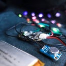
Now solder one of your three wires to the GND pin (ground), one to the Data Input pin and the last wire to the +5 V pin (power). Make sure you know which wire is soldered to what pin since you can’t trace it back through the tube. Solder a female plug to each of the three wires. Don’t forget to use some heat shrink to secure the easy to break soldering joints. With a heat gun or Epoxy glue the three milky acrylic circles on top of each other and wait until dry. Then center the circles on top of the inside of the acrylic petals and glue them together. After the glue is dry center the NeoPixel ring on top and apply glue around it. Don’t forget to secure the wires running around the ring to the back of the piece.
Step 13: Sew the Fabric Strips Onto the Dress


Now put the dress and top piece on the mannequin and figure out where you want to position the strips. Carefully open up the seams in the marked area as well as the waist seams behind the battery bag (lining and top layer). Now feed the fabric strips though the lining and top layer so the strips come out through the waist seam. Pin the strips with the wanted length in the right position and close only the top seam for now.
Step 14: Integrate Electrodes


Cut three squares out of conductive fabric. The first image shows where you have to place the electrodes inside the dress. I used a zig-zag stitch sewing the squares onto the lining. The electrodes need to be pushed tight onto your bare skin in order to pick up your heart beat. Otherwise the conductive fabric can't pick up the electrical signals running through your body. Now solder a wire (I recommend flexible silicon wire) onto a button snap. Prepare three wires in total, one for each electrode. Sew those button snaps behind the lining with the conductive fabric patch - between lining and top layer. It is important using conductive thread to connect the electrodes with the wire and later on microcontroller. Then guide all three wires through the dress until coming out of the open spot in the waist seam behind the battery poach. To protect the wires a little more I put them in a little piece of leftover fabric tube right where I sewed over them to close the open waist seam. Cut the three wires to your desired length and solder a female jumper wire onto each end. This is necessary to connect the electrodes with the Hart Rate Monitor Board. Remember it is important knowing what wire connects to what electrode.
So far so good. The dress is pretty much ready.
Step 15: Modify and Upload the Code


Now let's come back to the software and hardware:
After setting up your Photon and installing Particle Dev (step 3), download the heart rate monitor code.
If you open the file you will see two folders, one called photon and another one called processing.
Go ahead and open Particle Dev and choose File > Open... in the drop down menu. Navigate to your photon folder and click Open. On the left side, click on WorkingPhotonHeartRateMonitor.ino to open the code. Now change the numbers of LEDs defined in the code to the number of LEDs you're using in your project.
#define NUM_LEDS 24
For the dress, I used 24 LEDs. You can also change the number for the other pins if you're using different pins. The little chart gives you an overview. If you want to change the mode button pin, click on the buttons.h file and change the number 6 to the pin you're using.
#define MODEBUTTON 6
If you'd like, you can add a little push button to this pin to switch between live mode and some recorded heart beat data. It's a nice feature to have if the dress on a mannequin. After connecting the electrodes to your body (in next step), you can just open the serial monitor, record your own data and replace the numbers with your heart beats in the recordedData.h file.
Step 16: Assemble the Hardware


Before soldering all the electronic components onto a 'Perma-Proto Half-sized Breadboard' use a normal breadboard for testing your electronics first. Connect the heart rate monitor, button and LEDs to the photon pins defined in the code. Stick the electrodes to your body like shown in the picture, ensuring the electrodes match the correct pins. Now you can open the photon serial monitor and get your heart beat data over you local WiFi.
If you want to see the EKG diagram on your monitor you have to download Processing. In Processing, open the sketch in the processing folder and run the sketch by clicking on the arrow in the left corner. If everything is set up correctly, a window will open up and you can see the activity of your heart. It helps moving as little as possible and it takes a while until the biosignal is steady enough for a clean visualization. For more information and/or troubleshooting check out Sparkfun's Heart Rate Monitor Guide. You might have to modify the line in the sketch which contains Serial.list()[3] and change the number to whichever port your serial monitor is on. If you're unsure of the number, try 0 through 6.
Step 17: Solder Onto Perma-Proto


To connect our custom integrated e-textile electrodes with the board, and not the bulky sticky electrodes, solder a header onto each of the RA (right arm), LA (left arm) and RL (right leg) pins on the board.
If everything works, you can solder the components on a perma-proto board. I started with the photon, then the wires followed by the heart rate monitor in the end. Instead of soldering the three LED wires permanently onto the board, I used three (Data, VCC and GND) male jumper wires to connect them with the LED wires.
A 5V power bank as a power supply works great for the photon because it's rechargeable. You can also use it for charging other electronic devices like your smartphone.
Step 18: Connect Your Heart Signals to the IoT


Now you're all set and you can connect your heart activity to the Internet of Things.
Note that the photon always needs to be connected to a wireless network, otherwise it won't stop searching and your code will not run. In a future update I can improve it so that an internet connection is optional.
If you have any questions, don't hesitate to ask. Happy making.

Second Prize in the
DIY Dress Contest

Participated in the
Full Spectrum Laser Contest 2016


