

Introduction: Motion Activated Light With Arduino and HC-SR04 Sensor


I did this project long time ago to light up the kitchen when I open the back door.
The idea was when I open the back door, this light turns on for 15 seconds, which will give me enough time to reach the light switch on the opposite wall. Before this project, I had to walk in the dark to turn on the light.
This instructable assumes that you have working knowledge with Arduino and electronics in general and that you have already installed the Arduino IDE on your computer. Other wise I made sure to detail it as much as possible and took enough pictures to make as clear as possible. If you have any questions after reading through do not hesitate to contact me.
Happy building.
Step 1: What You Need for This Project


Electronic equipment:
Arduino UNO
HC-SR04 Ultrasonic Sensor
Power Relay (I used a Songle srd-05vdc-sl-c)
Cables:
A regular extension cord (Optional, because I didn't want to cut the cable attached to the light Bulb)
7 Watt light Bulb with a power cable (I took it from a Christmas decoration :) )
9 Jumper cables (3 male/female for the relay and 6 male/male for the Arduino and the HC-SR04)
Other:
Solderless breadboard
USB cable to connect the Arduino to the computer
Arduino IDE
Ruler (30 cm / 12 inches)
A small screwdriver
Step 2: Cut the Extension Cord

Separate the extension cord in half, about 10cm/4inches and cut one of the sides to expose the copper (see picture).
It doesn't matter which side you cut because the cord will be plugged into an AC power outlet (wall jack)
I tinted the exposed copper with a bit of solder but this is completely optional, you can just twist them together.
Step 3: Connect the Arduino to the Breadboard

First we will connect the Arduino UNO and the Breadboard:
I use red Jumper wire to connect 5V PIN on the Arduino to the red + rail on the breadboard
and I used a Black Jumper wire to connect the GND (ground) PIN on the Arduino to the blue - rail on the breadboard.
See picture for details.
Step 4: Connect the HC-SR04 to the Breadboard and the Arduino

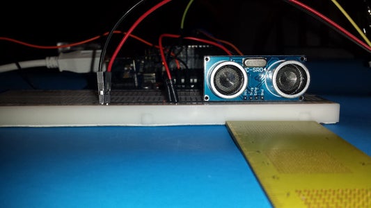
Place the HC-SR04 Ultrasonic sensor on the edge of the breadboard with the sensors pointing away from the board, see picture.
The HC-SR04 Ultrasonic sensor has 4 PINs
- The first PIN is the VCC and it will be connected with a red jumper wire to the red + rail on the bread board.
- The second PIN is the Trig or trigger and it will be connected to PIN 6 on the Arduino. The trigger PIN is used by the ultrasonic sensor to send out a sound wave.
- The third PIN is the Echo and it will be connected to PIN 5 on the Arduino. The echo PIN is used to pick up returning sound waves sent by the trigger.
- The last PIN in the GND or ground and it will be connected with a black jumper wire to the blue - rail on the breadboard.
Step 5: Connect the Power Relay to the Arduino, the Breadboard and the Extention Cord


The songle srd-05vdc-sl-c power relay has three pins on one side and three screw terminals on the opposite side.
The three PINs are labeled as follows: s, +, -
The S PIN is the signal and it is connected to PIN 9 on the Arduino
The + PIN is the 5V or VCC and it is connected with a red jumper wire to the red + rail on the breadboard.
The - PIN is the ground and it is connected with a black jumper wire to the blue - rail on the breadboard.
The screw terminal side of the power relay is labeled as follows: left NC, middle nothing, right NO
Here you will take the cut section of the extension cord and screw in one end to the middle (no label) and the other end to the NO using a small screw driver.
NO = Naturally open, which means that the circuit is open and no electricity is flowing through.
NC = Naturally closed, which means that the circuit is closed and electricity is freely flowing.
We will start with an open circuit = the light bulb is off, and when the relay receives a signal from the Arduino on the Signal PIN to close the circuit, the light bulb will turn on and we hear the distinctive "Click" sound of the power relay activating.
Before plugging in the extension cord in the AC power outlet, lets work on the sketch and upload it to the Arduino first.
Step 6: The Arduino Sketch
First I will try to explain the sketch with words:
Initially I define three variables which are the physical pins from the HC-SR04 "trigger and echo" and the power relay.
In the void setup, I start the serial monitor, define the Trigger and the Relay pins as outputs because they will output a result while the echo pin is defined as input because it will be waiting for information from the trigger pin.
The action happens in the void loop:
First I define two integers duration and distance to store the information gathered by the trigger. Then I tell the trigger to send a sound wave using the digitalWrite(trigPin, HIGH); command, then wait half a millisecond then I turn it off using the digitalWrite(trigPin, LOW); command. When the wave returns I store the information in the "duration" integer and activate the echo pin using the command pulseIn(echoPin, HIGH); Now we do some math to determine the distance, which is duration/2 then we divide this answer by 29.1 to get the result in centimeters.
The next step is to verify the result that we got: If the result is less than 13cm, execute the light subroutine, if not then do nothing. And display the result on the serial monitor.
The light subroutine:
When invoked, it activates the power relay pin, waits 15 seconds then it turns it off.
As simple as that :)
And now the Sketch:
#define trigPin 6 //Define the HC-SE04 triger on pin 6 on the arduino
#define echoPin 5 //Define the HC-SE04 echo on pin 5 on the arduino
#define bulb 9 //Define the relay signal on pin 9 on the arduino
void setup()
{
Serial.begin (9600); //Start the serial monitor
pinMode(trigPin, OUTPUT); //set the trigpin to output
pinMode(echoPin, INPUT); //set the echopin to input
pinMode (bulb, OUTPUT); //set the bulb on pin 9 to output
}
void loop()
{
int duration, distance; //Define two intregers duration and distance to be used to save data
digitalWrite(trigPin, HIGH); //write a digital high to the trigpin to send out the pulse
delayMicroseconds(500); //wait half a millisecond
digitalWrite(trigPin, LOW); //turn off the trigpin
duration = pulseIn(echoPin, HIGH); //measure the time using pulsein when the echo receives a signal set it to high
distance = (duration/2) / 29.1; //distance is the duration devided by 2 becasue the signal traveled from the trigpin then back to the echo pin, then divide by 29.1 to convert to centimeters
if (distance < 13) //if the distance is less than 13 CM
{
Light(); //execute the Light subroutine below
}
Serial.print(distance); //Dispaly the distance on the serial monitor
Serial.println(" CM"); //in centimeters
delay(500); //delay half a second
}
void Light() //Start the Light subroutine
{ digitalWrite(bulb, HIGH); //turn on the light
delay (15000); //wait 15 seconds
digitalWrite(bulb, LOW); //turn off the light
}
Attachments

Step 7: End Result
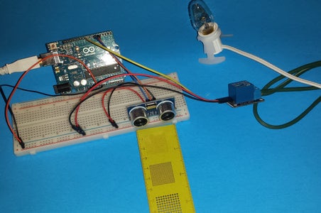

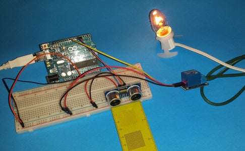
Once you verify and upload the sketch to the Arduino, plug the extension cord in AC wall outlet, the light will turn on if you place an object less than 13 cm in front of the HC-SR04.
I will make another instructable once I find a 3D print master to make this project look pretty.
I hope you like it.


