

Introduction: Moving Rainbow Arduino Sign


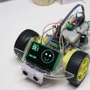

I am a volunteer at my local CoderDojo chapter, an organization that does software mentoring for kids 8-18. I try to get kids interested in computer science by teaching them to build fun Arduino projects that use color, motion and social project-based learning. We sit in a large room and when kids walk in the door I want them to be attracted by a colorful LED sign with lots of changing color patterns.
This project is also ideal for schools that have display cases that want to highlight the programming skills of students in classes or science clubs.
My design goal was to build an attractive sign you could build for under $20 in about an hour. My goal is to keep the design as simple as possible with a minimum of steps.
Step 1: Figure Out the Dimensions of Your Sign and Order LEDs

I use a plastic bin to carry my Arduino kits around. It is about 20 inches wide, so I decided to make my sign 19 inches wide. To keep the proportions of the word "ARDUINO" this implied that I need the sign to be about 5 inches high.
Since the word ARDUINO has 6 complex stroke letters and the simple letter "I", I calculated that each letter would need 7 or 8 LED pixels and the "I" would need only 4 pixels. I figured I could get by with a single 50 element LED string.
You can get these on e-bay for about $11 to $14 with shipping. Mine came in about a week.
Here are some of the search keywords you can use on e-Bay:
50PCS WS2811 RGB Full Color 12mm Pixels digital Addressable LED String
Here is a sample link on e-bay:
Step 2: Find Some Translucent Plexiglass and Sand Out the Glossy Finish


I visited a local surplus store and picked up a sheet of scrap translucent Plexiglas. The smallest piece they had was $8 and I could easily make 6 signs out of this piece. I used a jig saw to cut my 5X19 piece out and I sanded the edges down with sandpaper.
Since we will be hot-gluing the LEDs to the back of this we need to have a rough surface. I used 100-grit sandpaper, but I think you could use 200 grit also. The key is to get the shiny gloss finish out or the hot-glue will not stick.
Step 3: Print White Text on a Black Background

To display the letters I created a two-page PowerPoint presentation with white text on a back background. I then printed the slides on standard photocopier paper. Don't use a heavy stock paper since the light will not show through.
Step 4: Draw the Attachment Points Behind Each Letter

I used a very light pencil to put small points behind each letter. I counted the points to make sure that sure that I used 50 total on the sign. I ended up using 8 LEDs for the "A", "R", "D", "U", "N", 4 points for the "I" and six for the "O".
Step 5: Hot Glue the LED Pixels to the Back

This is the only tricky part to the entire sign where planning is key. I started with the "A" and glued the first 8 LEDs to it, ending with the pixel on the lower left (from the back). This allowed me to go to the middle of the "D" for the next 8 pixels. I had to put hot glue down for each letter and then I blew on it to have it cool before the LED would fall over. I originally had the hot-glue gun on "HIGH" but then I realized that by putting it on "LOW" it would cool faster.
Note, that you only have three inches of wire between each LED. If you need more distance you will need to cut the wires and solder in additional wire.
I have also found that if you have rounded tops on the LEDs you can use a belt sander to grind down the LEDs tops to a flat surface. This makes it easier to glue the LEDs to the Plexiglass.
Step 6: Add a Base
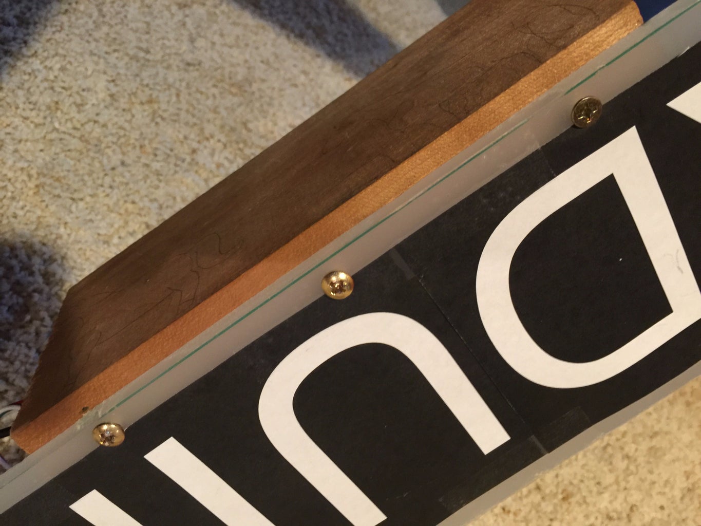
I also added a block of scrap wood to the base of the sign so it would sit upright. I drilled three holes in the Plexiglas and used 1 inch wood screws. The piece of wood I used was 3.5" X 8" and was 3/4 inch think.
Step 7: Mount the Breadboard With an Arduino Nano and Two Push Buttons
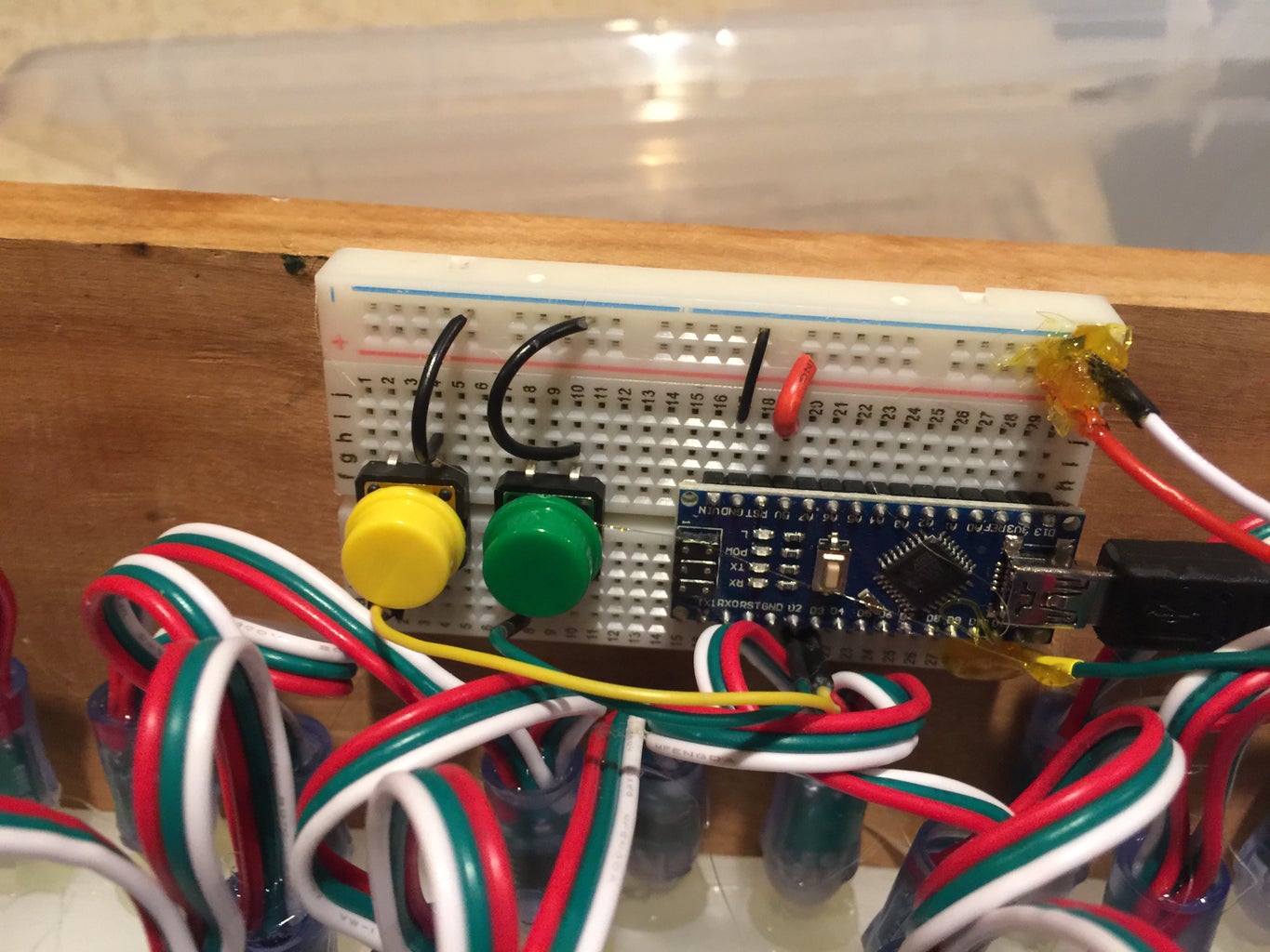
I mounted 1/2 size 400-connector solderless breadboard to the back of the wooden base board. The breadboards come with adhesive on the back that you just peel off and press to the board. I also put two "mode" buttons on the breadboard so students could skip through different display modes. One button goes forward and one backward. Some of the example programs just cycle through the display modes one at a time. The auto-cycle can also be the default mode when you first turn on the sign.
Step 8: Add a USB Cable and Power Converter

Although you can power the Arduino Nano from any USB port, I like to use an inexpensive USB 5 volt power converter to my sign kits. This makes it convenient to plug in anywhere. You can find these on e-Bay for under $1.
Here is a sample:
http://www.ebay.com/itm/Universal-5V-1A-AC-USB-Power-Adapter-US-Plug-Home-Wall-Travel-Charger-New-FY-/272513040872?var=&hash=item3f730b01e8:m:mtJE5fSj-U2SCEtgtghvc_w
Step 9: Video and More to Explore
The example program has many other sample pattern modes. Here are a few other ideas to explore:
- Add a Passive Infrared (PIR) sensor so that the sign pattern only goes on when their is motion.
- Add a pattern to light up each letter one by one.
- Add a potentiometer dimmer to change the brightness.
- Add a potentiometer to change the speed of each pattern.
If you are interested in the software you can visit the "Moving Rainbow" github site here:
https://github.com/dmccreary/moving-rainbow
there is also a on-line book that gets auto-generated each time there is a new checkin here:
http://moving-rainbow.readthedocs.io/en/latest/REA...
one example multi-mode program is here:
https://github.com/dmccreary/moving-rainbow/blob/m...
The Moving Rainbow site also has an instructor's guide for teachers and mentors.


