

Introduction: Multiplexing With Arduino - Transistors (I Made It at Techshop)


The purpose of this instructable is to give a step by step instruction on implementing multiplexing using transistors. The first few steps will introduce Multiplexing, Transistors and when to use them.
I was working on a binary clock project at techshop and I decided to make a instructable on Multiplexing with Transistors. I plan later to also make an instructable on Multiplexing using shift registers when finished I will Link it .
To copy my example in the later steps you will need the following.
9 - LEDs
6 - NPN transistors
6 - 1k ohm resistors
3 - current limiting resistors (220 ohm)
Arduino Uno
Breadboard
jumper wires
I will always recommend tayda electronics for these parts, they have great pricing and products for hobbyists. Sometimes if you check their facebook page they give 15% coupons on entire orders! http://www.taydaelectronics.com/
Step 1: Transistors Background


Transistors play multiple roles but they are basically a electronic switch. That is exactly how we are going to use them for multiplexing.
I'm not really going to go into how they work or anything but just think of it as an electric switch. I will be using NPN Transistors, which are generally most commonly used. There is a Emitter, Base and Collector, make sure you know which pin is which when putting a circuit together. Current flows from the Collector to the Emitter and the Base enables / disables this current flow. This is essentially what allows it to be a switch.
This also is useful if you want to have two different power sources or you need a lot of current. Since the Base is separate from the Collector and Emitter they can be powered separately. How is this useful? Well all microcontrollers have a Digital Pin (GPIO) maximum output current which usually doesn't go much higher than 200mA. If you have multiple LEDs on at once then you may exceed the 200mA which is not good for the microcontroller. So using a transistor, the microcontroller doesn't need to supply the current to the actual component such as an LED. Not really related to multiplexing but you can also use transistors to have a microcontroller control a different power source, also how a relay is used.
The second image above is the basic schematic for the anode and cathode schematic using transistors. (Note: the capacitor on the Anode circuit isn't required). The circuit isn't actually a anode or cathode, however I refer to them like that because the output of the anode circuit connects to the anode of the LED. While the cathode circuit connects to the cathode of the LED. The anode of an LED is where current comes into the component and the cathode is where current leaves the component. So of course the anode transistor circuit supplies the VCC and the cathode transistor circuit supplies the Ground.
Transistors I'm using: http://www.taydaelectronics.com/2n3904-npn-general-propose-transistor.html
Step 2: Multiplexing

When multiplexing think of it as rows and columns, depending on what your working with (in our case LEDs) your always going to have rows and columns. On the last step you saw the schematic for the anode and cathode, one will be the rows and the other the columns.
The picture in this step shows a group of 9 LEDs, there are 3 rows and 3 columns. The rows and columns do not matter what order they are in or which one is the anode/cathode but the hardware must match the software! In the case of the picture the row is the "dominant" over the column. What I mean by that is if you look at the steps, one row is set to on while certain columns are set to power the LEDs. How is this done? Well depending on the code you need to make one "dominant" I do this by having a row function that calls a column function each time the row changes.
Since there are 3 steps and the final images says "what you see", how does that work? Well if the change is happening lets say every 1ms then the human eye cannot tell the difference, much the same way a refresh rate or frames per second work on a TV. So truly only one row of LEDs are turned on at one time, but to the eye they all seem to be on at once.
Multiplexing ratio improves even more when you add more rows and columns! say you want a 16 by 16 display, that's 256 LEDs. With Multiplexing that's 16 rows, 16 columns so 32 pins to control 256 LEDs! 32 is still quite a lot of Digital pins (Arduino only has 12...) but that's where you could use shift registers to use even less pins.
Now this does bring up a problem, in order to constantly view this image the code must keep changing the rows every few ms so all rows appear to be on. So things like delays cannot be used with multiplexing. Unfortunately Arduino code seems to rely heavily on delays... The solution? using one of the Atmega328s Timer/Counters, in my final example you can see the code to implement one of the timers.
Step 3: Making a Multiplexing Schematic

You need to decide what row / column you want to be that anode or cathode, but I actually doesn't matter. In my case as you can see in the schematic I picked the row to be the anode and the columns the cathodes.
As you can see in the schematic since the rows are the anode, each row of the LEDs anode are connected to each other. It's the same case for the columns, all the cathodes of the LEDs are connected.
Where Multiplexing is really different from connecting a LED directly to a pin is due to how ground is controlled. If you just have a LED connected to a pin the cathode of the LED is generally connected to the common ground. With a multiplexed circuit the microcontroller controls the availability of the ground. This allows you to disable entire rows or columns because the circuit cannot be completed due to having no ground.
In any case this is an ideal circuit, however for the anode you do not necessarily need a transistor. If you wish to use the microcontroller and draw current from it you can directly hookup the pin to the anode of the LEDs. However it's not ideal because your drawing that current from the microcontroller, like I said in step 1 the microcontroller has a maximum current supply. The anode doesn't necessarily need a transistor but the cathode MUST have one. You still need to enable/disable the ground for the multiplexing to work.
The second picture shows the schematic practically the same as my physical circuit i used for my example. The next step will show how to write your program for multiplexing.
Step 4: Multiplexing Code
In order to implement the multiplexing you will need to code in a certain way. It is actually not that complicated, lets say the row is "dominant" over the columns. This means the one row transistor is turned on while the column of that row is ran through once. After that you move to the next row and do the same again and again until it repeats!
The problem with refreshing the LEDs fast enough to not notice is you cannot have a synchronous system. This means you cannot have delays that last for a extended period of time. So if you have a delay of 1 second, where ever the rows and columns are it will only display that one for the entire second.
The easiest way to make this happen is to use two functions where one calls the other repeatedly. Since in this case rows are "dominant" over columns we will have two functions lets call them:
- Display_LED()
- Column_Load()
So here's some sudo-code:
void Display_LED(char a, char b, char c)
{
Column_Load(a);
digitalWrite(transistor_pin1, HIGH);
delay(1);
digitalWrite(transistor_pin1, LOW);
// Repeat depending on number of rows
}
So the function Display_LED above is the "dominant" function for rows. Again you can use either rows or columns as the dominant it doesn't really matter. You first call the column function to set those transistors on or off. Then you set the certain row transistor high. I have a short delay so the LED is on for 1ms. if you change it to 1000ms you can really see each one change. Thats why you cant use delays in the rest of your program. From there you turn the transistor off and repeat the code with changing from a to b and switching to the second row.
void Column_Load(char LEDs)
{
if (LEDs_on == 0x07)
{
digitalWrite(colum1_transistor, HIGH)
digitalWrite(colum2_transistor, HIGH)
digitalWrite(colum3_transistor, HIGH)
}
}
This function is pretty simple, depending on what value the parameter has you set the LEDs how you want them. If you use PORT_ and DDR_ then it is actually simpler code to write than using digitalWrites. In most cases I set the vale as a hexidecimal value so if i input a 0x03 that means LED 1 and 3 are turn on while 2 is off.
The next step is an example of a 3x3 LED array using the following functions above. The only difference is the rows and columns are reversed.
Step 5: 3 by 3 LED Display Example

example code:
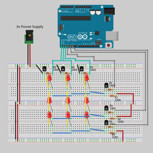
You can see the picture with the LEDs displayed this was done using the code below. The code is also attached as a .ino file. The LEDs lit are set by the 0x02,0x05,0x02. the decimal representation of those hex values is 00000010,00000101,00000010. You can see how those values match the display.
If you want to try this out for yourself the code is available below and just copy the circuit from step 3!
/* Transistor Multiplexing 3x3 LEDs
By: Marty Peltz
Date: 7/19/2013
Purpose: Control 9 LEDs in a 3x3 pattern using multiplexing.
Used in Martin Peltz's Instructiable
*/
/**** variables ****/
char col1_cathode = 0;
char col2_cathode = 1;
char col3_cathode = 2;
char row1_anode = 3;
char row2_anode = 4;
char row3_anode = 5;
void setup()
{
// Set Pins to outputs
pinMode(col1_cathode, OUTPUT);
pinMode(col2_cathode, OUTPUT);
pinMode(col3_cathode, OUTPUT);
pinMode(row1_anode, OUTPUT);
pinMode(row2_anode, OUTPUT);
pinMode(row3_anode, OUTPUT);
// turn off all GPIO pins
digitalWrite(col1_cathode, LOW);
digitalWrite(col2_cathode, LOW);
digitalWrite(col3_cathode, LOW);
digitalWrite(row1_anode, LOW);
digitalWrite(row2_anode, LOW);
digitalWrite(row3_anode, LOW);
}
void loop()
{
display_LED(0x02,0x05,0x02);
}
/**** display LED function ****/
/* Purpose: Call this function with the hexdecimal parameter you wish to display
* Notes: This function controls the Cathode, in my case controlling the columns
*/
void display_LED(char c1, char c2, char c3)
{
row_anode(c1); // Call row_anode with first hexdecimal value
digitalWrite(col1_cathode, HIGH); // Display the first column
delay(1); // Wait a short delay so the LED is on for 1ms
digitalWrite(col1_cathode, LOW); // disable first column before continuing
row_anode(c2); // Call row_anode with second hexdecimal value
digitalWrite(col2_cathode, HIGH); // Display the second column
delay(1); // Wait a short delay so the LED is on for 1ms
digitalWrite(col2_cathode, LOW); // disable second column before continuing
row_anode(c3); // Call row_anode with second hexdecimal value
digitalWrite(col3_cathode, HIGH); // Display the third column
delay(1); // Wait a short delay so the LED is on for 1ms
digitalWrite(col3_cathode, LOW); // disable third column before continuing
// (note try changing the 1ms to 100ms-1s you will see a difference)
}
/**** Cathode (columns) function ****/
/* Purpose: Take paramater value and turn on related pins
* Note: Due to using Arduinos digitalWrite you must set the pins,
* however if using DDRx/PORTx you can just apply a hexdecimal value to set the pins on a port.
*/
void row_anode(char LEDs_on)
{
if(LEDs_on == 0x00)
{
digitalWrite(row1_anode, LOW);
digitalWrite(row2_anode, LOW);
digitalWrite(row3_anode, LOW);
}
else if(LEDs_on == 0x01)
{
digitalWrite(row1_anode, HIGH);
digitalWrite(row2_anode, LOW);
digitalWrite(row3_anode, LOW);
}
else if(LEDs_on == 0x02)
{
digitalWrite(row1_anode, LOW);
digitalWrite(row2_anode, HIGH);
digitalWrite(row3_anode, LOW);
}
else if(LEDs_on == 0x03)
{
digitalWrite(row1_anode, HIGH);
digitalWrite(row2_anode, HIGH);
digitalWrite(row3_anode, LOW);
}
else if(LEDs_on == 0x04)
{
digitalWrite(row1_anode, LOW);
digitalWrite(row2_anode, LOW);
digitalWrite(row3_anode, HIGH);
}
else if(LEDs_on == 0x05)
{
digitalWrite(row1_anode, HIGH);
digitalWrite(row2_anode, LOW);
digitalWrite(row3_anode, HIGH);
}
else if(LEDs_on == 0x06)
{
digitalWrite(row1_anode, LOW);
digitalWrite(row2_anode, HIGH);
digitalWrite(row3_anode, HIGH);
}
else if(LEDs_on == 0x07)
{
digitalWrite(row1_anode, HIGH);
digitalWrite(row2_anode, HIGH);
digitalWrite(row3_anode, HIGH);
}
}
Attachments

Step 6: 3 by 3 LED Example - Multiple Displays
extended example code:
In this case I implemented a Timer by setting the Atmega328's registers. This allows for a 1 second timer that is asynchronous so it wont cause delays in the display. To set the register you really need to look at the Atmega328's datasheet.
When the timer interrupt goes off every 1 second, i have a counter increase by 3 to display the next set of values in a array. The array has values to use for the display.
To see the example look at the attached file.
Step 7: Conclusion
I hope this instructable was helpful, once you understand the concept multiplexing is actually quite easy.
I plan on making another instructable to do multiplexing with shift registers. It's not much more compliciated other than some additional coding, circuitry and you can use a lot less pins!
If you have any questions feel free to ask!


